 Anders Nielsen
I've been thinking a LOT about the best way forward for the 65uino.
Ideally you should be able to make it from whatever you have lying around - basically as long as you have a 6507/6504, a ROM and a 6532 you should be good to go.
If you don't use the crystal oscillator inverter circuit though, only a single gate is used on the hex inverter, so I thought it was time for an optional minimisation - and put in a single gate SOT23-5 inverter so you can use that instead of a DIP14 '04/14.
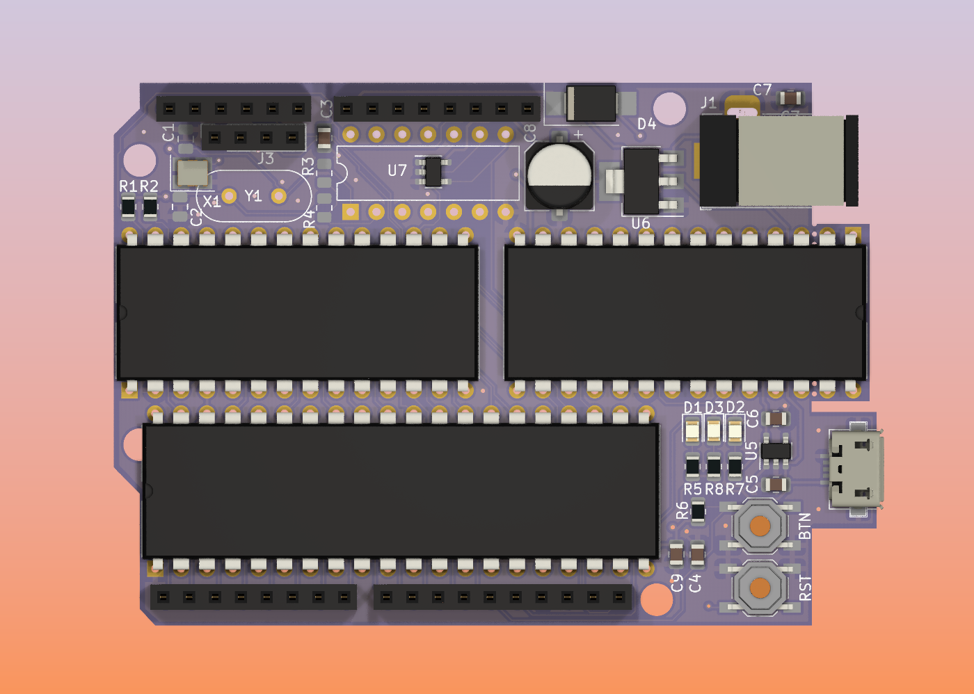
The idea here is that if you're comfortable with fine soldering for the SOT23-5 3v3 regulator and SMD oscillator, soldering another inverter shouldn't change things much - and if you're not comfortable with it, you might skip the 3v3 regulator and use the crystal oscillator inverter circuit instead.. Or have a PCB house do the SMT assembly.
Either way, I decided to make the SMT oscillator the default clock source since 1MHz crystals aren't actually that easy to come by but decided to leave in all the hackability. Philosophy: Make it easy to make one no matter if you want to do a lot of soldering or a little.
I really like the idea of making it so you can get a board in your hands and you just have to solder pin headers and sockets to the board and you're good to go - maybe I'll put a kit like that on Tindie, who knows!
And if you noticed the title of this log - yes, don't forget the pullups. Even though i2c peripherals usually have enough pullup oomph it's bad practice not to at least have pads for i2c pullups - so I added them on the bottom side. Now they can be added later if they turn out to be needed for something - but I've set the value to NC for now though.
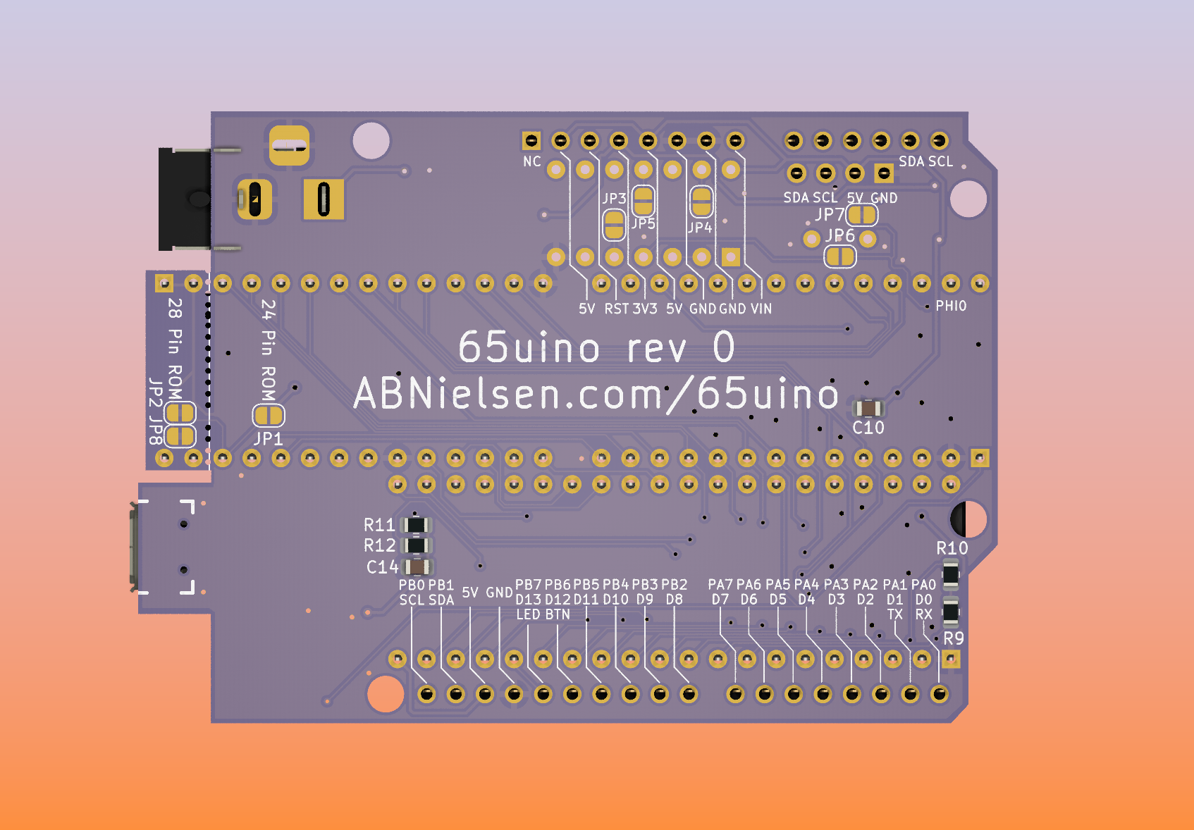
Same goes for pullups on the serial lines since it might be good practice - especially since the current code assumes the RX pin to be high unless we're in the middle of a serial transaction.
In the fringe case that someone would want to install an AT28C256 EEPROM that can technically be programmed in circuit(by code in RAM for instance) I added JP8 so it's easy to free the RW pin. However, that still requires you to at least NAND the ~OE line with the 6507 ~WE as well (and no NAND gate on board ATM). Doesn't hurt and makes it more hackable - you can also use it for banking ROM if you want to(that might be more fun!).
Happy hacking!
Discussions
Become a Hackaday.io Member
Create an account to leave a comment. Already have an account? Log In.