I use a TP4056-based LiPo charger with a micro USB connector. The charging current is 1A according to the manufacturer. But since I use a 250mAh LiPo battery, I need a lower charging current (max. 250mA). The following excerpt from the datasheet shows that the resistor at pin 2 of the TP4056 determines the charging current. So I have to change the resistor accordingly.
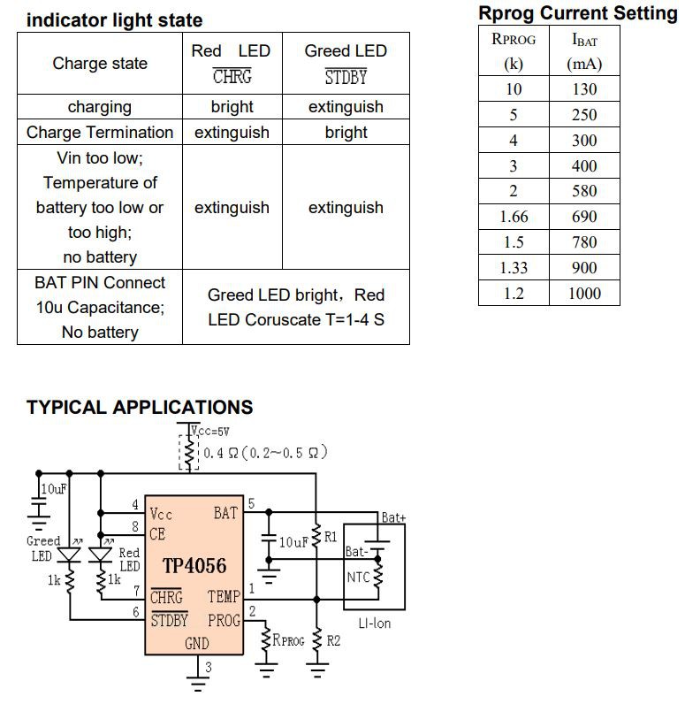
The charging current can be accurately calculated by the following formula:
The according resistor is located in the middle of the lower side of the PCB and is labeled with "122":
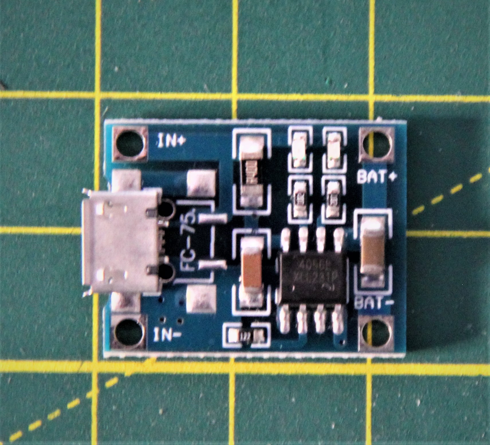
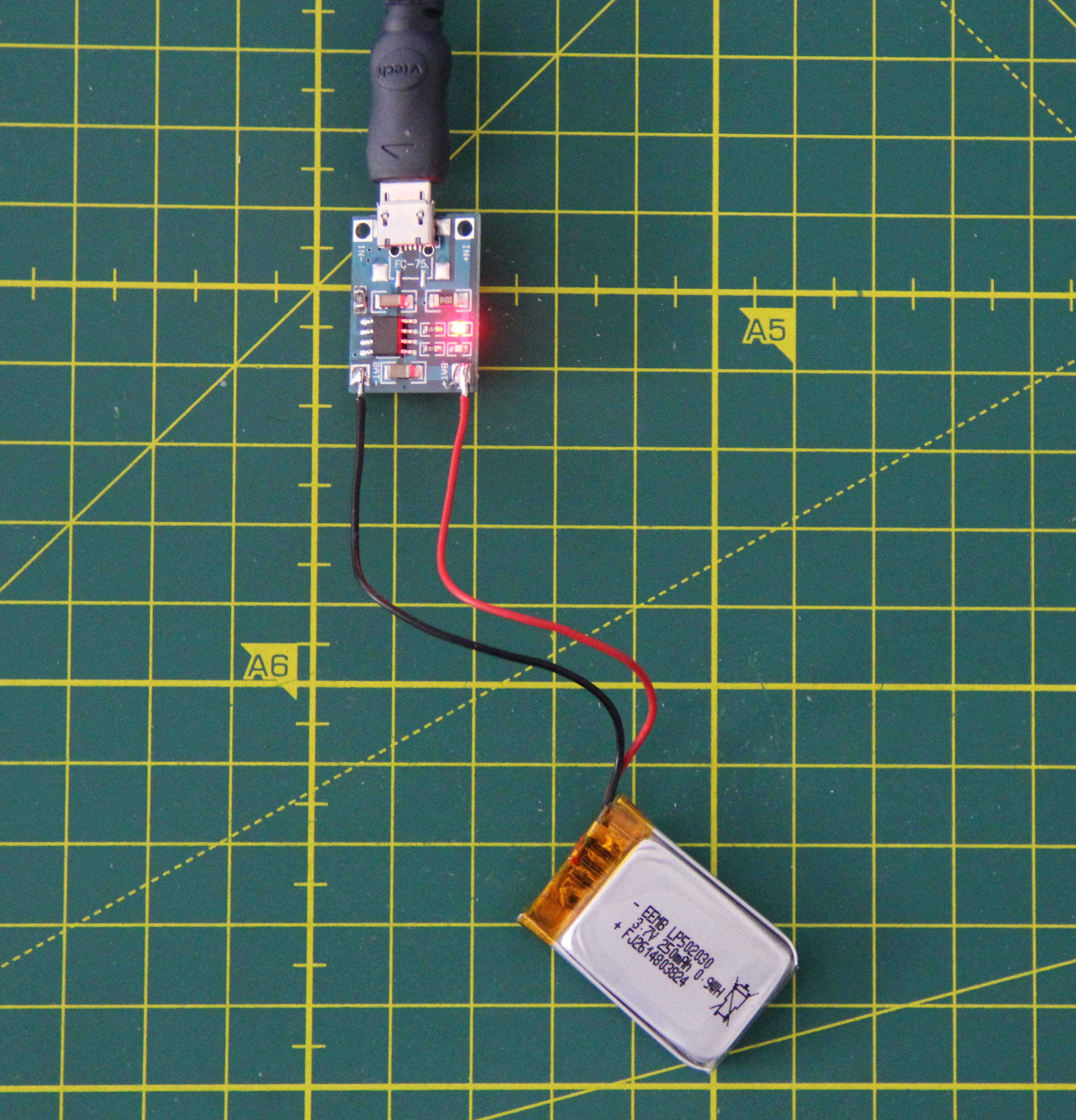
Testing the charger after modification:
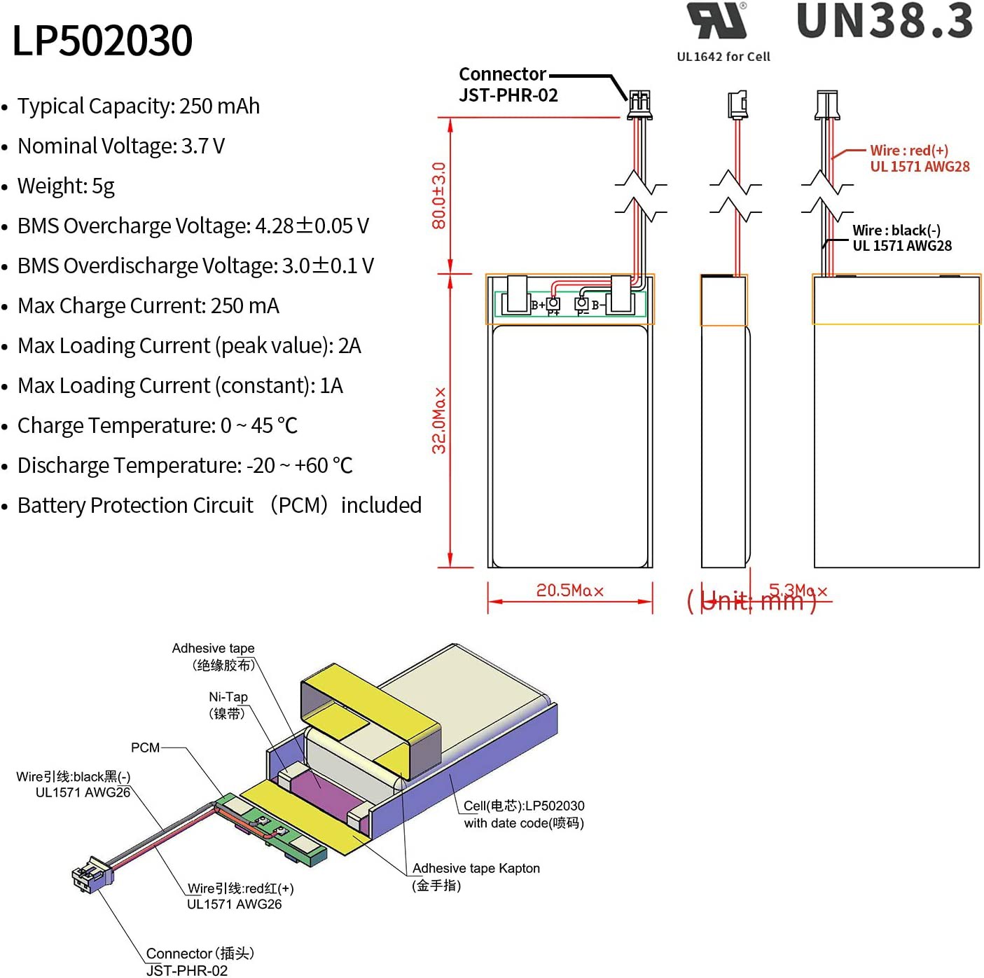
The LiPo battery I use has the following characteristics:
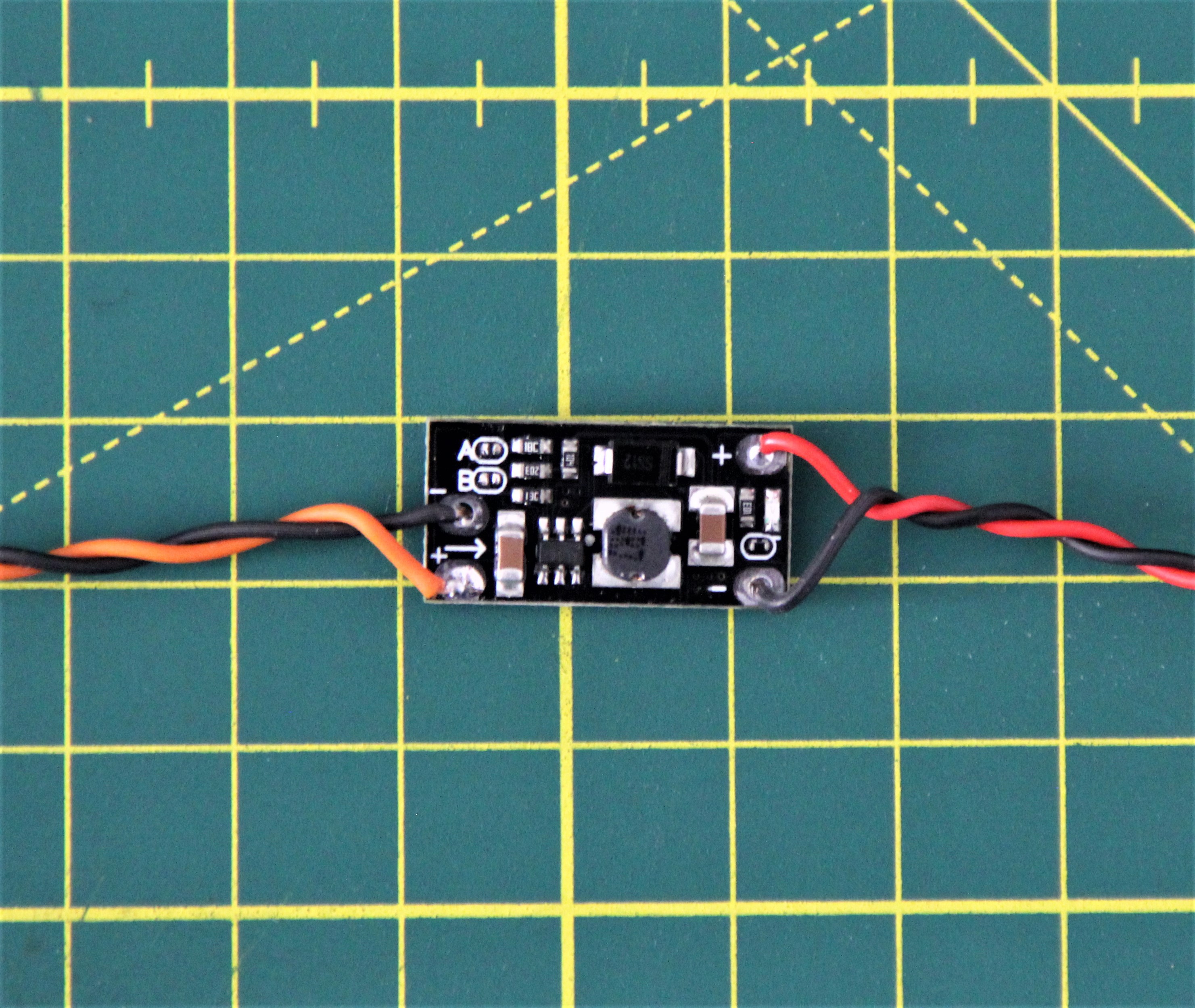
The first DC-DC step-up converter I tested was total garbage. Even with a constant input voltage, the output voltage fluctuated consistently over 1 to 2V. The following one is fine. The output voltage can be programmed via two solder jumpers.
 M. Bindhammer
Discussions
Become a Hackaday.io Member
Create an account to leave a comment. Already have an account? Log In.