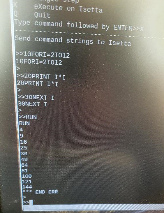
A major milestone was reached today ! The original Apple 1 BASIC, programmed by WOZ, is running on the real Isetta hardware ! It runs on the intended 12.5 MHz (80nS cycle time).
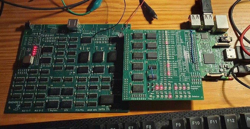
For character I/O, there is a synchronous serial link with a Raspberry Pi. The screen and the keyboard of the Raspberry Pi are used to communicate with Isetta.
Here you see a screenshot of the RPi screen. After the ">>" (generated by the RPi) the RPi reads a full input line, echoing it on the screen. Then, after a CR (return), the line of characters is sent to Isetta Apple Basic, and Basic again echoes the characters to the screen. Then the output of the Basic interpreter follows, and the Basic prompt ">". Note that there is an "*** END ERR" because there is no END statement at the end of the program.
PROGRAMMER
Quite some work had to be done after the prototype was soldered. I had to make a Python program on the Raspberry Pi to program the microcode into the three microcode flash chips. On the programmer board (described in the previous log) a small change was needed. This Python software can also execute arbitrary microcode on Isetta, and run a test program that tests hardware functions.
The programmer can grab the clock of Isetta, by putting the first 74AC163 clock divider into LOAD mode, and providing a new clock (SW generated by RPi) to the first two preset inputs of the 163. The transistor that transferred this clock was, unsurprisingly, not fast while switching OFF, and I suspected that was the reason that I sometimes got a bad working instruction during singlestepping. This transistor also did the 3.3V to 5V translation. I replaced it by a simple diode with a 1N5 cap in parallel. It's a poor man's level converter. At the high RPi 3V3 level, 0.7 V is added by the diode so the ac163 sees around 4V on its input. That worked, errors now occurred rarely, and could be handled by a retry mechanism in the programmer.
How does the application program (the 4K Basic interpreter) get into the main RAM ? I could modify the programmer such that it writes to RAM instead of microcode flash. But I already had a mechanism in place that would also work with a fully stand-alone power-on and reset. A certain part of the microcode copies the BASIC interpreter program from the microcode flash to the main RAM, soon after reset.
COMMUNICATION
Next thing was communication (characters in, characters out) between RPi and Isetta. It should also work when Isetta generates VGA output, so we are handling a single bit directly after the horizontal interrupt. (That is generated by a simple hardware timer).
The bit handling should always take exactly the same amount of cycles, independent of the data send or received, otherwise there will be jitter in the generated VGA output.
When the VGA output and keyboard are working, we still need this interface to the RPi to transfer files to or from Isetta. We could also use the RPi screen as debugging output while an application runs on the VGA screen.
Since it should also be possible that a PS/2 keyboard is connected to Isetta, the choice was made to use the same receiver hardware and software for the keyboard as well as for data coming from the Raspberry Pi. Since it uses open collector outputs, both clock and data signals can simply be tied together. This combination was not foreseen when the PCB's were designed, so a few wires had to be added.
Communication RX receive driver
The keyboard has two lines, KB_CLK and KB_DATA. Both lines are driven by a open collector output on a standard PS/2 keyboard (pullup resistors in Isetta). If no information is sent, both lines are high. The keyboard receive driver will be able to receive scancodes that are sent by the keyboard. It has the following states:
- Wait for startbit. If the clock line has a falling edge, and the KB_DATA line is low, the startbit is valid and we proceed to the next state. If the data line is high at this falling clock edge, we stay in this state.
- Read databit. There are 8 of these states. If the clock line has a falling edge, the data line will be sampled and its value will be shifted into the keyboard-read register. Bit 7 in this register will be the bit that was sent first. This will be repeated 8 times. After that, we will continue to the parity-bit state.
- Read parity bit. If the clock line has a falling edge, the data will be read but it's value will not be used. But the value of the keyboard-register will be transferred to the keyboard buffer. The keyboard buffer can contain 255 values. There is no check if it is full. (Assumption is that the SW works faster than I can type).
- Read stopbit
The keyboard-receive system will also be used to transfer information from the Rasberry Pi to Isetta. The microcode programmer pcb has two open collector outputs for this purpose, that are (on Isetta) directly connected to the two wires coming from the keyboard. On the RPi this uses GPIO27 and GPIO2.
So, with a simple program on the RPi, the RPi keyboard can be used for Isetta. Instead of scancodes, ASCII codes will be sent over the connection. In the future, this ASCII encoding might be slighty changed, so that it does not overlap with scancodes, and Isetta can see if the info comes from a PS/2 keyboard or from the RPi.
Note that a PS/2 keyboard sends the LSB first, while the above receive system stores the first received bit in
the MSB (used because it gives simpler microcode). So Isetta receives reversed scancodes.
Communication TX transmit driver
The same keyboard driver will also handle traffic in the other direction (This is NOT the system that is used to send information to a PS/2 keyboard ). This uses a third wire called GP_OUT1, that is an output for Isetta and an input for the RPi. It is called GP_OUT1 because it can be used for other purposes when this TX function is not used.
The output is synchronous, clocked by the KB_CLK signal that is generated by the RPi. It requires that the RPi sends a keyboard byte in order to receive the TX information. The RPi must send a low startbit, and if there is no key to send, the databits should be all ones so Isetta sees a FF character and can dismiss it. Sending FF also provides a good synchronisation on the startbit.
In Isetta, data to transmit must be put into the transmit buffer. It can hold 255 characters.
The keyboard states have the following functions for TX:
- Wait for startbit. If the clock line has a falling edge, and the KB_DATA line is low, the startbit is valid and we proceed to the next state. If the data line is high at this falling clock edge, we stay in this state. The tx-register is loaded from the transmit buffer, but if the transmit buffer is empty, the tx-register is set to FF. The empty/non_empty state will be remembered in a tx_state register. So, if there is no data to send to the RPi, the RPi will receive a FF byte.
- Read databit. There are 8 of these states. If the clock line has a falling edge, the tx-register will be shifted left, and the bit that is shifted out will be put on the GP_OUT1 line. This will be repeated 8 times. After that, we will continue to the parity-bit state.
- Read parity bit. If the clock line has a falling edge, it will, if tx_state is 0, increment the pointer to the transmit buffer.
- Read stopbit
In each line interrupt, this RX+TX code will take approx. 16 cycles.
Changes to Apple Basic
Apple Basic uses memory locations for its character I/O. In Isetta, the 8080/Z80 IN/OUT instructions
will be used for I/O. These IN/OUT instructions were also added to the instruction set of the 6502 (with exactly the
same opcode as on the 8080/Z80, possible because 6502 has many unused opcodes).
At this moment, port 0x31 is used for RPi/KB input as well as output.
- IN 0x31 ; Reads KB scancode or input from RPi. Returns byte in ACC. When no byte available, returns ACC=0 with Z_flag=1.
- OUT 0x31 ; Writes character in ACC to RPi, and when the buffer is full, returns ACC=0 with Z_flag=1.
addr = 0xe3d5;  // address where bytes must be changed in output routine

memory[addr++] = 0xD3; // OUT (opcode 0xD3)
memory[addr++] = 0x31; // port 0x31
memory[addr++] = 0xF0; // BEQ  (try again if buffer was full)
memory[addr++] = 0xFC; // -4
memory[addr++] = 0x60; // RTS


addr = 0xe003;  // address where bytes must be changed in input routine

memory[addr++] = 0xDB; // IN (opcode 0xDB) new keyboard-input instruction
memory[addr++] = 0x31; // port nr
memory[addr++] = 0xF0; // BEQ, loop while buffer is empty
memory[addr++] = 0xFC; // -4
memory[addr++] = 0x09; // ORA #80
memory[addr++] = 0x80; //
memory[addr++] = 0x60; // RTS,  char in acc.
A lot more to do, a few things:
- Getting VGA output to work
- Make a simple file system in the 32Mb serial flash
- Get PS/2 keyboard working
I bought a PS/2 keyboard online for about 20 Euro, but it keeps sending the same data at fixed intervals. A little online searching learned that my keyboard model only works after it receives a reset command. So that will be a small hardware and software change to add transmitting a reset message to the keyboard.
Supporting a PS/2 Mouse would also be nice...
Discussions
Become a Hackaday.io Member
Create an account to leave a comment. Already have an account? Log In.