PROGRAMMING MANUAL
An Isetta Programming Manual was made, that describes all features that are available to the assembly program.
You can find it in the File Section.
It describes most of the I/O ports.
It also describes the video system, bankswitching, ports used for the Blitter, and describes a debugger that I made.
MICROCODE INTRO
One of my plans was, to have some microcode support for writing to the screen.
Writing to the screen, in Z80 (or 6502) assembly language, can be very tedious. The screen is pixel based. There are several complications:
- in 640x400 mode, there are two pixels per byte
- we might have graphics encoded as 2 bits per pixel (4 colors), this must be converted to 4 bits per pixel
- We might have transparent pixels (for sprites). So sometimes, in a byte, one nibble must be written but the other stays the same.
- the upper and lower half of the screen are in different memory banks
- perhaps the 4-bit color pixels must be converted to another 4-bit color code
A Z80 assembly program to do this will be difficult to write, especially because it should be quite fast (to get the screen written in an acceptable time).
MICROCODE FEATURES
To get a good performance, it would be better to write screen handling in microcode. On Isetta, programming in microcode has the following features:
- A microcode instruction is 24 bits, and is totally different from a Z80 or 6502 instruction.
- While the main purpose of the microcode is, to implement Z80 or 6502 instructions, it can also be used to do other functions.
- A 24-bit micro-instruction can be fetched from microcode flash memory while a data byte is transferred to/from data memory (Harvard style). A micro-instruction always executes in a single cycle (80 nS).
- The 24-bit instructions are addressed by the instruction register (8 bit), a step counter (4 bit), a page register (4 bit), and the flag F (1 bit).
- The micro-instructions can read and write flags, and have conditional execution, that lets the F flag choose between two micro-instructions.
- During execution of a Z80/6502 instruction, when the required steps are done, a micro-instruction will load the instruction register (IR) from an address that is in the program counter (PC++), reset the step counter to 0, and might set the page register to a new value.
- If, at the end of the 16 steps, the instruction register (IR) is not loaded again, the IR will automatically increment, because the lower 4 bits of the instruction register is also a counter. So a sequence of micro-instructions can be 256 cycles long. If IR is still not loaded, it will go back to the first of these 256 steps.
- If the instruction register is loaded, it does not have to be loaded from the PC address. It can also be loaded with a constant (to jump to a fixed next instruction), or can be loaded from a register in memory. It is possible to write simple programs without using the program counter.
MICROCODE DETAILS
What do the micro-instructions do, more in detail ?
1) Read the next 24-bit micro-instruction (pipelined), from one of two 'tracks' chosen by the F flag.
2) Determine memory address and memory bank. Memory address can come from:
- the data pointer (DPH/DPL), or
- the program counter (PC) with optional auto-increment, or
- a small fixed value (included in the 24-bit instruction). This is divided in two ranges (selected by microcode):
- A) A fixed range of 64 bytes
- B) A selection between two other ranges of 64 bytes. Selection is done by the output bit EXX. The BC, DE and HL registers of the Z80 are stored in this range.
There is an option to set the lowest address bit to 1. This is useful to read the MSB of a word, without having to increment the pointer (of course, the word must be aligned). Another option forces the address bits 8 - 15 to zero, useful for zero page addressing.
3) Read a 8 bit data value from memory (except when writing of course), and put the result on the databus (Literal values must be stored in memory before they can be used).
4) One of the following:
- Do ALU operation with inputs databus and a register (A or T), write result to a register
- Write 8-bit register A (accumulator) or T (temp) to memory
- Write to an output location or read from input location
- jump to another microcode sequence (16 pages of 256 sequences each), by writing the databus value to the IR register, and selecting the new microcode page. The jump takes an extra cycle before it is effective.
5) Microcode can select if one of the flags F, C or N must be written. 3 bits select what is written to F.
6) Write register A or T to video output, when that is enabled (one 6-bit pixel or two 4-bit pixels per cycle)
7) The flag "F" selects from which track the micro-instructions are read. Used to implement
conditionals in microcode, without using jumps
All these 7 actions are done TOGETHER IN THE SAME CYCLE, with 12.5 million cycles per second.
The most important ALU operations are:
one operand: ld inc dec asl rol lsr ror (ld passes the databus operand unchanged)
two operand: add sub adc sbc and or xor res ( res (reset) means: ( X and not Y), used for Z80 RES instruction )
The ALU functions have several options for the carry input (3 bits select the carry input). The ALU operation is selected by 5 other bits.
The possible registers to write to, are:
A (Accumulator)
T (Temporary)
DPL data pointer low
DPH data pointer high
PCH program counter high (At same time, PCL is loaded with old PCH value)
BNK memory bank register
The flags are:
F selects from which track the micro-instructions are read
C Carry (available to Z80/6502 programs)
N Negative (also called S, sign) (available to Z80/6502 programs)
TC Temporary carry. Not visible to Z80/6502 instructions. Available after every instruction.
DTC Delayed version of TC, for accessing a TC that was produced a few cycles ago.
Instructions asl, rol are implemented by connecting both adder inputs to the databus (done by the logic units).
Instructions lsr, ror are implemented with a 256-byte table in RAM, filled by Isetta directly after reset.
Note that since the datapointer (DPH/DPL) and program counter (PCH/PCL) can only address the memory, it seems that their value is not accessible (for instance for storing a return address in a CALL/JSR instruction). However, registers DPL, PCH, PCL are accessible, using a trick described in log 13.
Note that for operations with memory data, most RISC processors need two cycles because they do either a memory access or an ALU function. For such situations, Isetta takes only one cycle (memory read and ALU function in one cycle), and can be considered being a 25 MIPS processor (however, with 8 bit data size).
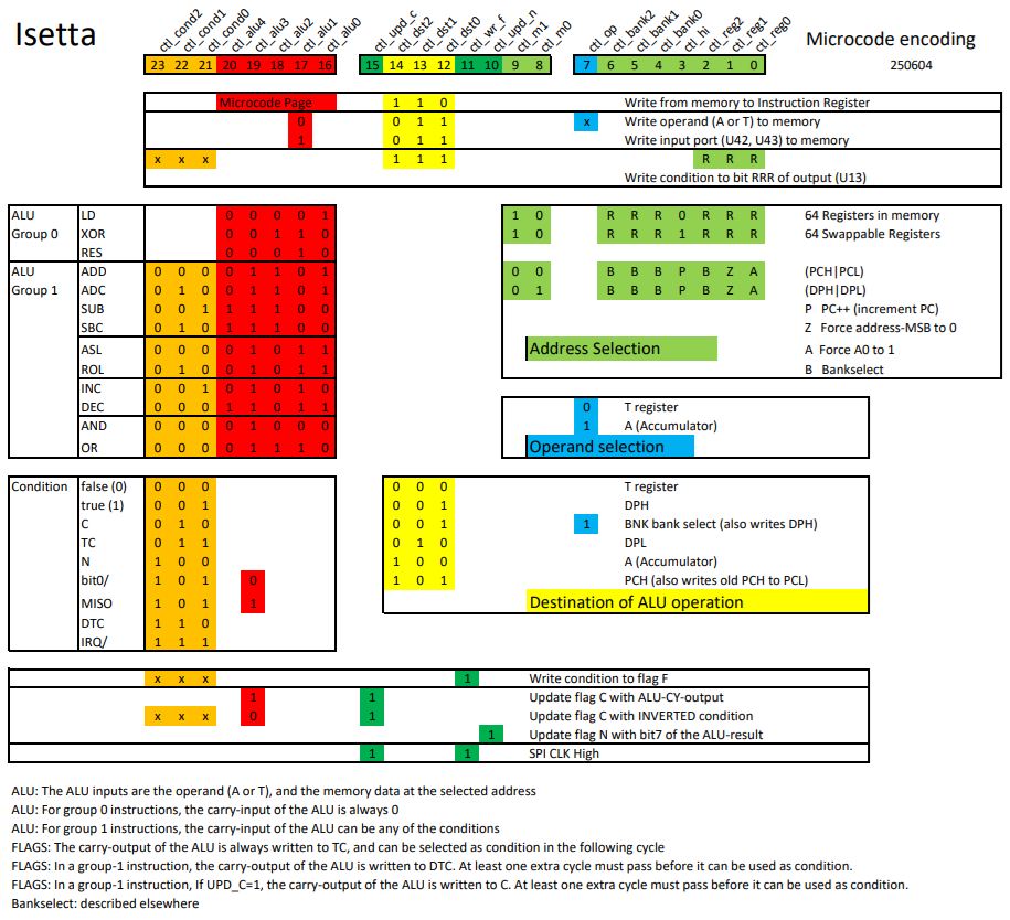
MICROCODE ENCODING
(The picture becomes slightly larger when you click it).
Some more details of the microcode encoding:
The main instruction type is determined by the 3-bit (yellow) destination selection.
An instruction can be in group 0 or in group 1. The group is determined by microcode bit 19 (ctl_alu3).
For group 0 instructions, the flag F can be written at the same time, with any condition, independent of the main instruction type.
Near the top of the overview, you see the instruction to write to the instruction register. You see that there is a 5-bit microcode page written, while the Isetta has only 16 pages of microcode instructions.
Normally, when writing to the instruction register, the next sequence will start at step 0 (from 16 steps). But when the lowest page bit (ctl_alu0) is set, it starts at step 8 of a sequence. So, when an instruction sequence is 8 steps or less, we can use the upper 8 steps for another 8-step sequence.
The flag C (Carry) can written with an inverted condition. The main use of this, is write C with the inverted carry, to complement the carry flag. This was needed for the Z80, as described in this log . It is also used with condition 'bit0/' (bit0 of the result in the previous cycle) to write bit0 to the carry, together with a right-shift operation, to put the bit that was 'shifted out' into the carry flag. It can also be used to write C with a fixed 0 or 1 value.
There are two features for efficient reading from the SPI bus (for the onboard serial flash and the micro-SD card):
1) The ROL (rotate-left), instruction is used as a shift register to convert the serial SPI data to a parallel byte. Use the DPL register as source and also as destination for the instruction. But instead of shifting the carry into the byte, let the condition select the MISO signal from the SPI bus.
2) By making ctl_upd_c and ctl_wr_f both 1, the SPI clock will be high. This can be done at the same time as another instruction. But keep in mind that the value in C and F will be destroyed.
Together, these two features make it possible to read from the SPI bus with only two cycles per bit.
The bankselect system is described in [this log].
MICROCODE ALU INSTRUCTION ENCODING
The above picture gives an almost complete description of the heart of Isetta. But it does not describe the exact function of the five ALU control bits. So I describe that here:
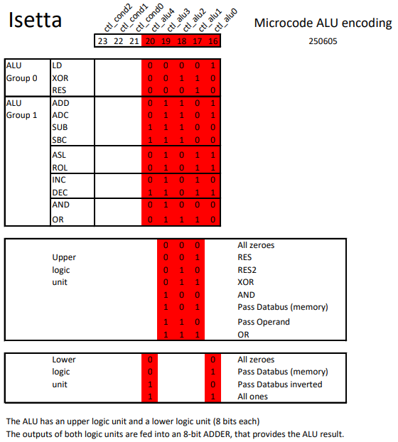
The upper and lower logic units are described in project log #2. The control system has been a little simplified, but the principle is the same. The three control signals of the upper logic unit are the DCBA control signals, with the A signal always being 0. For the lower unit DCBA signals, B is equal to D and A is equal to C.
The function RES2 has not been discussed before. It is the same as RES, but with its operands swapped.
MICROCODE ADVANTAGES
When the program should run very fast, using microcode on Isetta helps a lot, because:
- The program counter can be used as second data pointer, eliminating many datapointer load instructions
- The T register can be used as second accumulator
- In a Z80/6502 program, only the hardware registers A and PCH/PCL are transferred from one instruction to another. But in microcode, all hardware registers A, T, PCH/PCL, DPH, DPL are available to the program.
- A Z80/6502 needs, for every instruction, a cycle to fetch the opcode from memory. These cycles are eliminated when programming in microcode. (a real Z80 takes even two cycles to fetch the opcode).
- By putting a selector value in the instruction register, CASE statements can be very fast
- In many cases, conditional jumps are eliminated due to the two-track microcode, so they take no time
- In many cases, Z80/6502 instructions take cycles to write the flags correctly, even when these flags are not used. In microcode, you only have to write flags if that is needed for your program.
MICROCODE DISADVANTAGES
- The microcode is in parallel flash memory, and a programming device is needed to change it
- The microcode must check the interrupt-request signal regularly. This interrupt occurs every 400 cycles. It must always be serviced, otherwise the functions for screen output, keyboard and mouse input will not work correctly (But checking the interrupt request can be done in zero cycles).
- Not very memory efficient. A micro-instruction, on its two 'tracks', takes 6 bytes (2 x 24 bits). And several micro-instructions might be needed to do the work of a single Z80 or 6502 instruction.
INTRODUCING THE BLITTER
After glorifying the microcode, it won't be a surprise that I wrote screen functions in it.
The Blitter (Wikipedia) is a microcoded unit that is specialized in writing to rectangular sections of the Hires screen.
To use this, you first setup the parameters, using special OUTPUT ports. After that, you start the blitter by writing the action code to the P_BLITCTRL output port.
Most commands require three kinds of parameters: (most parameters are 16 bits)
- memory source base address, coordinates, line-length
- screen coordinates
- rectangle size
A few commands use FILL1 and FILL2 that both specify a color.
The Blitter supports the following actions (not all of them fully working yet):
D_BMCOPY ; COPY source to screen
D_BMCOPYCNV ; COPY source to screen, converting SymbOs color numbers to Isetta color numbers.
D_BMSKIP ; Copy source to screen, except where source has color 0 (transparent)
D_BMSAVE ; Save from screen to source memory address
D_BMTEXT ; TEXT write a character from a font map to the screen. Font map is 1bpp.
D_BMFILL ; Fill a screen rectangle, alternating colors FILL1 and FILL2 (in most cases they are the same)
D_BMFXOR ; Fill a screen rectangle using XOR operator, alternating colors FILL1 and FILL2
Most of these use the format of two 16-color pixels per byte (4bpp).
The COPY and SKIP will possibly also support four 4-color pixels per byte (2bpp) as source.
The blitter is fully described in the Isetta Hardware Manual, that you can find it in the File Section.
MOUSE
I also have more code for the mouse now... I have a mouse pointer on the screen, that I can move with my mouse (Taken for granted nowadays, but it will not work without hardware or code that implements it).
Before the mouse pointer graphic is placed, a D_BMSAVE is used to save the background. Then, the mouse pointer is copied to screen using D_BMSKIP.
When the mouse is moved, the background is restored with a D_BMCOPY action, and then the mouse pointer is placed at the new position.
OK.... you can conclude that I didn't spend a lot of my free time watching TV.
Discussions
Become a Hackaday.io Member
Create an account to leave a comment. Already have an account? Log In.