The new pcb design was finished. I did not send it yet for production, because experience says, that within ten minutes of the final submit for production, I think of something that I forgot in the design. So I just wait a few days before ordering.
What changed (w.r.t. ISA2442 version):
- The wire modifications, as on prev version, are no longer needed
- slightly changed form factor, to better fit in the housing
- Have a 1.5 W sound amplifier on board, can now directly connect a speaker. The
output for an amplifier is also still on board.
- Due to speaker dimensions, a bigger housing is used, RM2055M (instead of RM2055S)
- Have a 'wakeup' button at the front. (A SymbOs command can put Isetta asleep). The power
LED will be off while Isetta is asleep.
- Several changes to improve EMC behaviour
- Amount of Microcode flash ROM can be doubled, now 32 instead of 16 microcode pages.
(The option to use 8-cycle instructions was removed for this.)
- Max number of consecutive microcode cycles is now 512 (was 256). Now it is easier
to display 640 pixels per line (two pixels per cycle, so 320 consecutive cycles)
- The selection between 640 or 320 pixels per line is simpler now (uses ctl_upd_n)
- The 4 blinkenlights were removed
- Added a LED to indicate file read/write
- Changed the optional WiFi module to XIAO ESP32S3 (WiFi + Bluetooth BLE)
- The WiFi module has an option to add LoRaWan
- One extra IC used. And one for the sound amplifier.
New Option connectors:
- I/O A: 20 pin connector. Bus for parallel input/output. Has 8 datalines, 3 address lines.
- I/O B: 20 pin connector. Supports 4 input and 4 output bits. Also useable for alternative power
supply (and battery backup). This option can also select a lower CPU speed
for less power consumption.
- I/O C: 40 pin connector. A board to give more video modes can be connected here.
- I/O D: 20 pin connector. Connects to RPi. This was "I/O C" on prev version. Removed some unused signals.
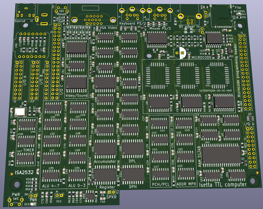
This is the 3D impression of KiCad:
Discussions
Become a Hackaday.io Member
Create an account to leave a comment. Already have an account? Log In.