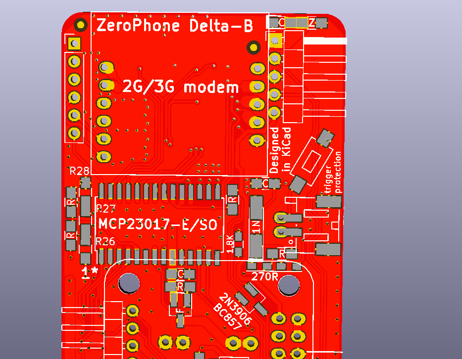
Hi! Here's a long overdue worklog about a new revision that was released two months ago =D It's called Delta-B, the only changes from Delta are bugfixes; this time that's actually true - not like Gamma=>Delta which was planned to be like a bugfix-only revision, but had to get lots of additions.

Why? When I received an offer for PCB sponsorship from JLCPCB (funding the free kit batch), I didn't even have an assembled&working Delta ZP. My previous ZP experience taught me that it's important to fully test PCB additions before releasing the next version, and I decided to seize the moment and release a version of PCBs I could consider "stable". So, I went on a series of Twitch streams (which you might remember), assembling a Delta ZeroPhone and testing it, then designing the new revision. What were the problems?
- The charger-to-USB switchover circuit didn't work properly. What's that? It's a circuit I added to allow powering the USB power from 5V on the charger input when the charger is connected. How do you fix it if you have the Delta (not Delta-B) PCBs? Here are the instructions.
- The I2C HAT EEPROM didn't work properly. Why's that there? To allow us to distinguish between different PCB revisions in software. How do you fix it if you have the Delta (not Delta-B) PCBs? Here are the instructions. Also, I've designed and will soon receive PCBs to make the fix easier, so you don't have to deadbug a fix and can just ask me for a small board - again, in case you ordered the Delta PCBs, the Delta-B has all of that built in.
- There are some silkscreen and footprint fixes - some values were incorrect, some polarities were unobvious, some footprints (1) (2) were wrong or confusing... Basically, stuff that could trip people up during self-assembly - and since Delta was designed for ease of self-assembly, it only made sense to look out for such bugs
- Certain charger&protection boards (with "flaps" at the BAT/OUT end) would mechanically interfere with two components. Small, but annoying problem - hopefully, fixed.
- I didn't know that there's a certain range of voltages that the comparator I'm using can compare - basically, it can't compare voltages in the 0 to VCC range, only in the 0 to VCC-2V (0 to 1.3V) range, things outside that are the hardware version of undefined, and of course I picked reference&compare voltages in that range. Still haven't figured that one out fully, for now, I'm not paying much attention to the comparator (and will consider removing it in the future revision).
That's mostly it. As usual:
- GitHub PCB release (also has gerbers and schematics exported neatly into separate .ZIPs, ought to automate that)
- OSHPark links: front board, back board, keypad board, 18650 board, speaker adapter (not hosted by me, this time - someone else got there first! =D )
- New shiny thing! Assembly helper that's based InteractiveHtmlBom, in other words, it's wonderful and check this out: front board and back board. Irreplaceable if you want to do self-assembly.
That's it for now. Hope to publish something else interesting here soon - otherwise, this blog is kinda abandoned =)
 Arya
Arya
Discussions
Become a Hackaday.io Member
Create an account to leave a comment. Already have an account? Log In.