 gedm-dev
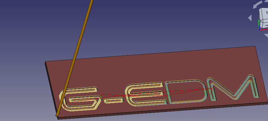
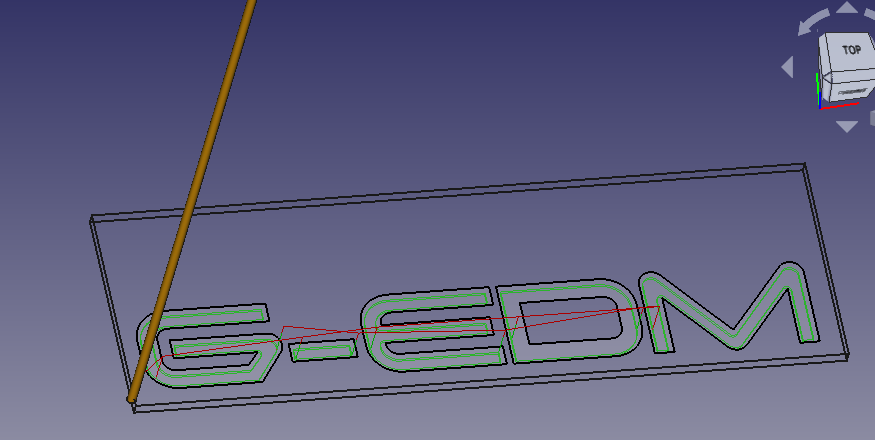
Ok. X and Y is working. That is a good thing. But the GCode created for Lasers with a bigger laserdot diameter to simulate the electrodes can turn out very ugly.
A laser moves from on side to the other and doesn't care about overshooting the contours. Normally the dot of a laser is small so this isn't a problem. But a 1.5mm "dot" can create an ugly outer shape.
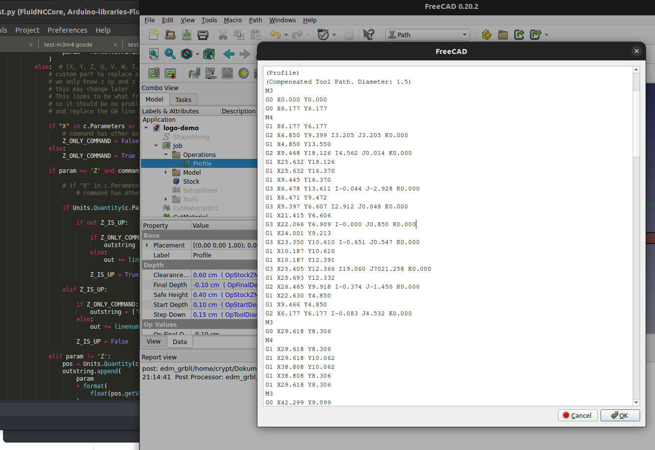
I'm currently modifying the internal GRBL postprocessor that is part of freecad.
First goal is to get electrode up/down movements working instead of using Z axis motions. This could be done within the G-EDM software too but to keep it simple and clean a modified postprocessor would be a good way.
Generating GCode with freecad is not as hard as it looks.
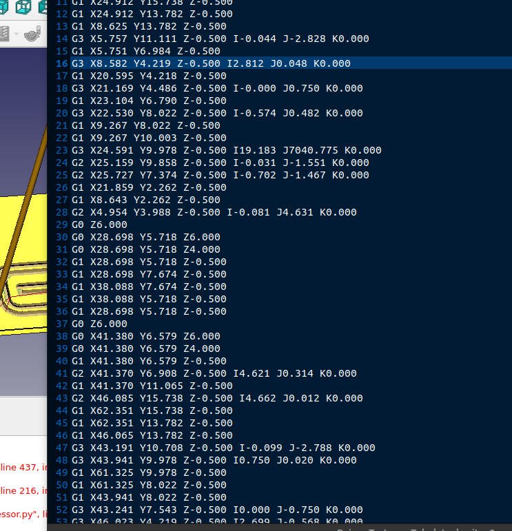
Update: Looks like it is possible with GRBL-Plotter to compensate the tool diameter and prevent ugly contours with negative toll diameter values and the output of the customized FreeCAD postprocessor looks promising too:
Discussions
Become a Hackaday.io Member
Create an account to leave a comment. Already have an account? Log In.