 gedm-dev
Currently the GEDM uses a simple voltage divider network on the spark PSU as only source of feedback. This only works with a current controlled PSU and it is not perfect.
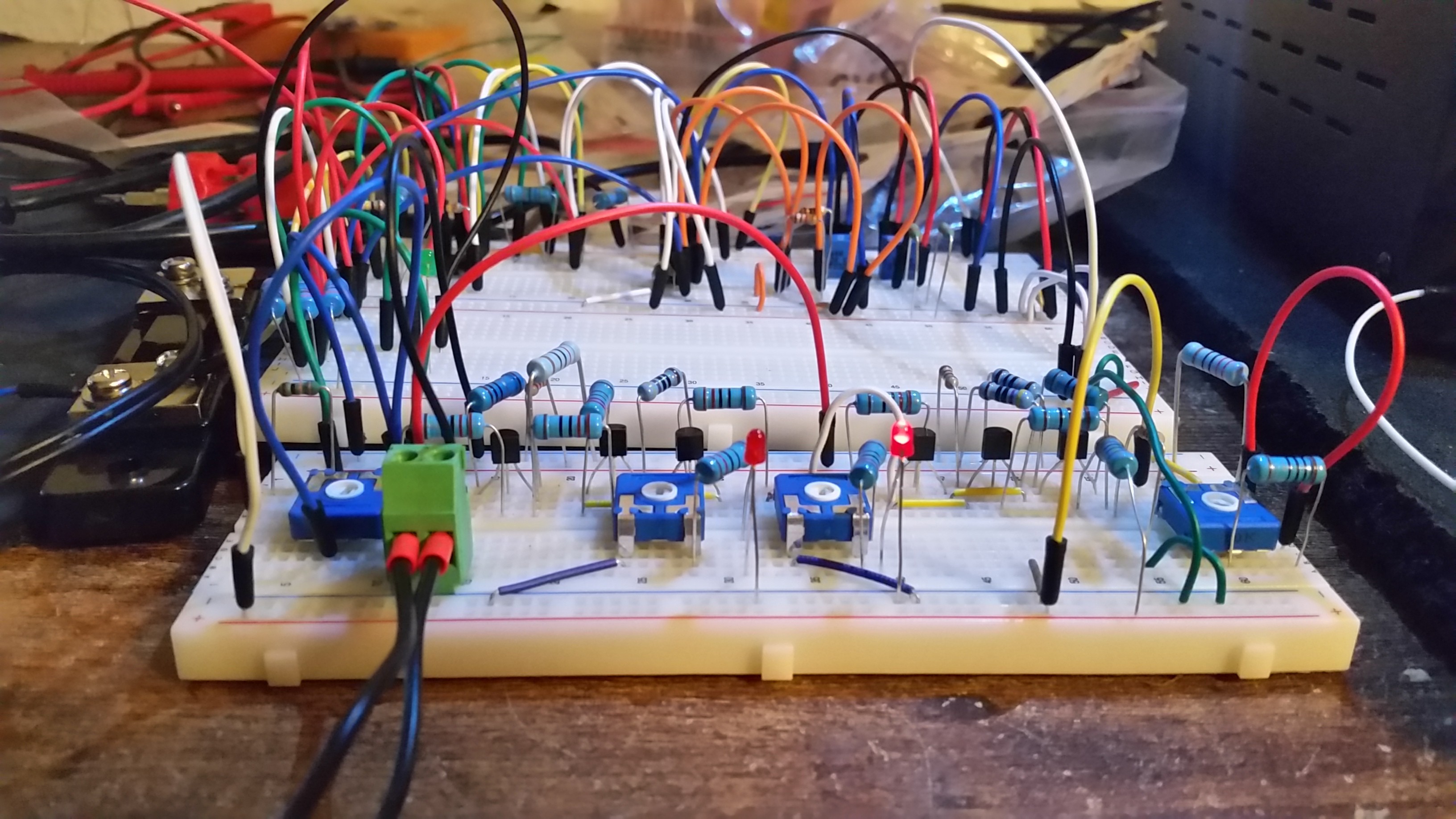
So it was time to get into real gap sensing or at least something that is able to sense the current that runs through the electrode.
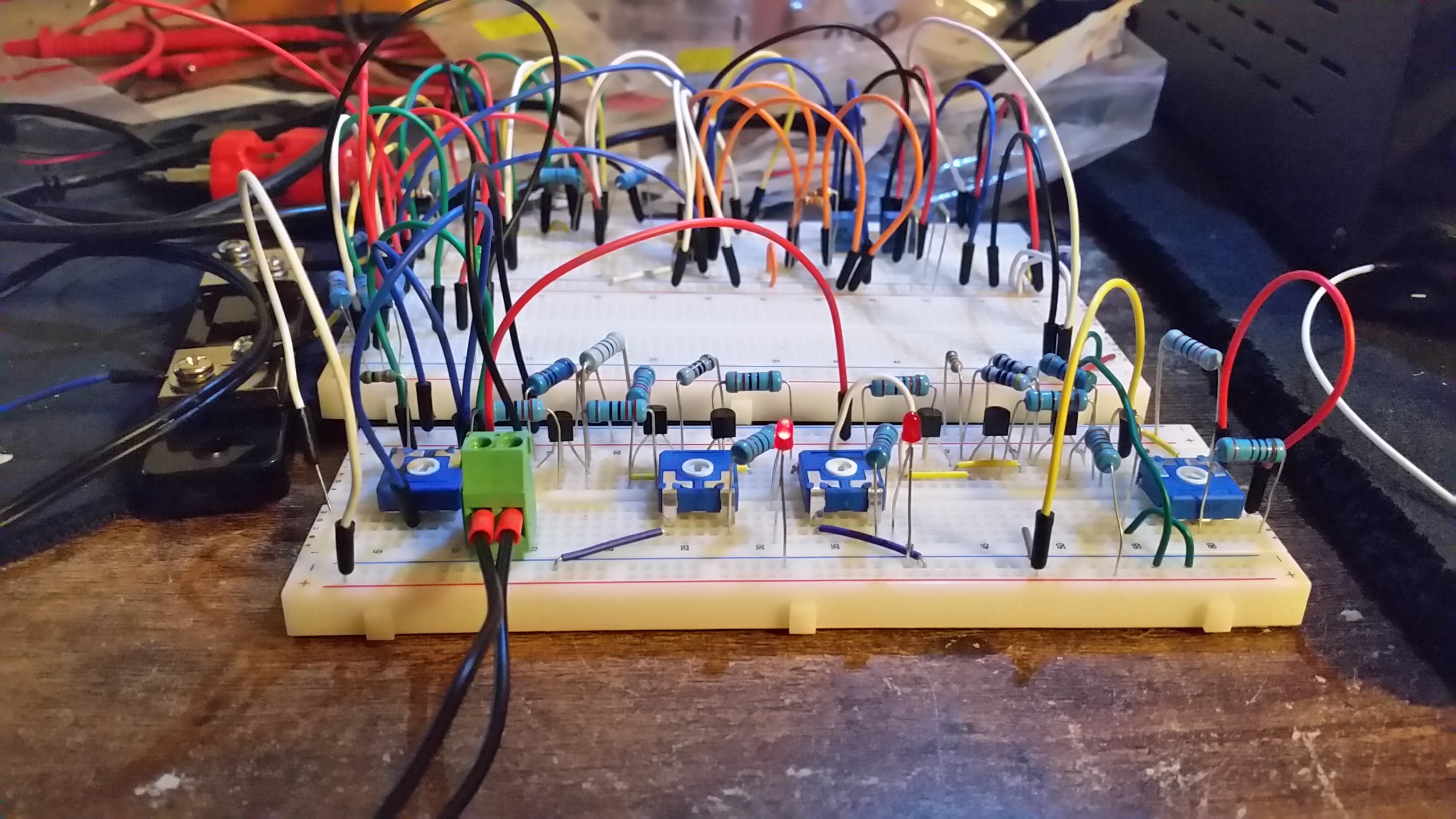
Wasn't easy to get some usable results but the circuit designed for sensing seems to work on the breadboard.
It provides analog feedback and two digital feedbacks with variable setpoints.
This is not a replacement part for anything. The current pulseboard is powerful and works acceptable well. In combination with this extension it should be possible to get very accurate control over the EDM process even with a linear PSU.
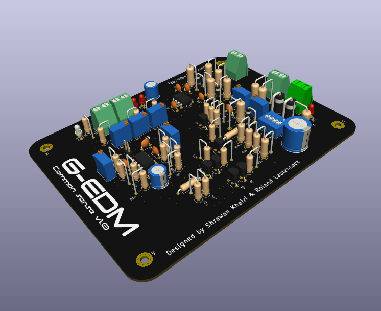
The circuit was designed with the help from Shrawan Khatri

Discussions
Become a Hackaday.io Member
Create an account to leave a comment. Already have an account? Log In.