I wrote an earlier log about RAM and ROM but this log supersedes that one. Earlier on I was trying to jumper existing modules to map everything into the 64k space (bios at $0000, cartridge rom (on the same rom chip) at $4000 and ram at $8000 upwards). This may have worked for certain scenarios but the MSX has the concept of 4 'slots', each of which covers the whole 64k. Software can switch these in and out (see last log) and so for a fully compatible MSX system I really need to replicate that slot selection system.
In a previous log I had a working PPI (as far as I'd tested it) which contains, among other things, the 'primary slot selection register'. That maps each 16k 'page' of the address space to one of four physical slots. My PPI design as it stands combines the bits of that register with A15 and A14 to provide two slot selection lines.
If I'd thought this through, I would have decoded that further into the 4 slot selection lines (active low) on the PPI module and connected those to lines on the backplane because that makes it very easy to enable each memory module depending on which 'slot' it wants to be in. (eg BIOS should be in slot 0, RAM is conventionally in slot 3, cartridge slots are 1 and 2.)
For now, I've got a '138 on a breadboard with 4 active-low outputs connected to the 4 spare lines of the standard RC2014 bus, which I'm designating 'Slot Selection 0,1,2 and 3':
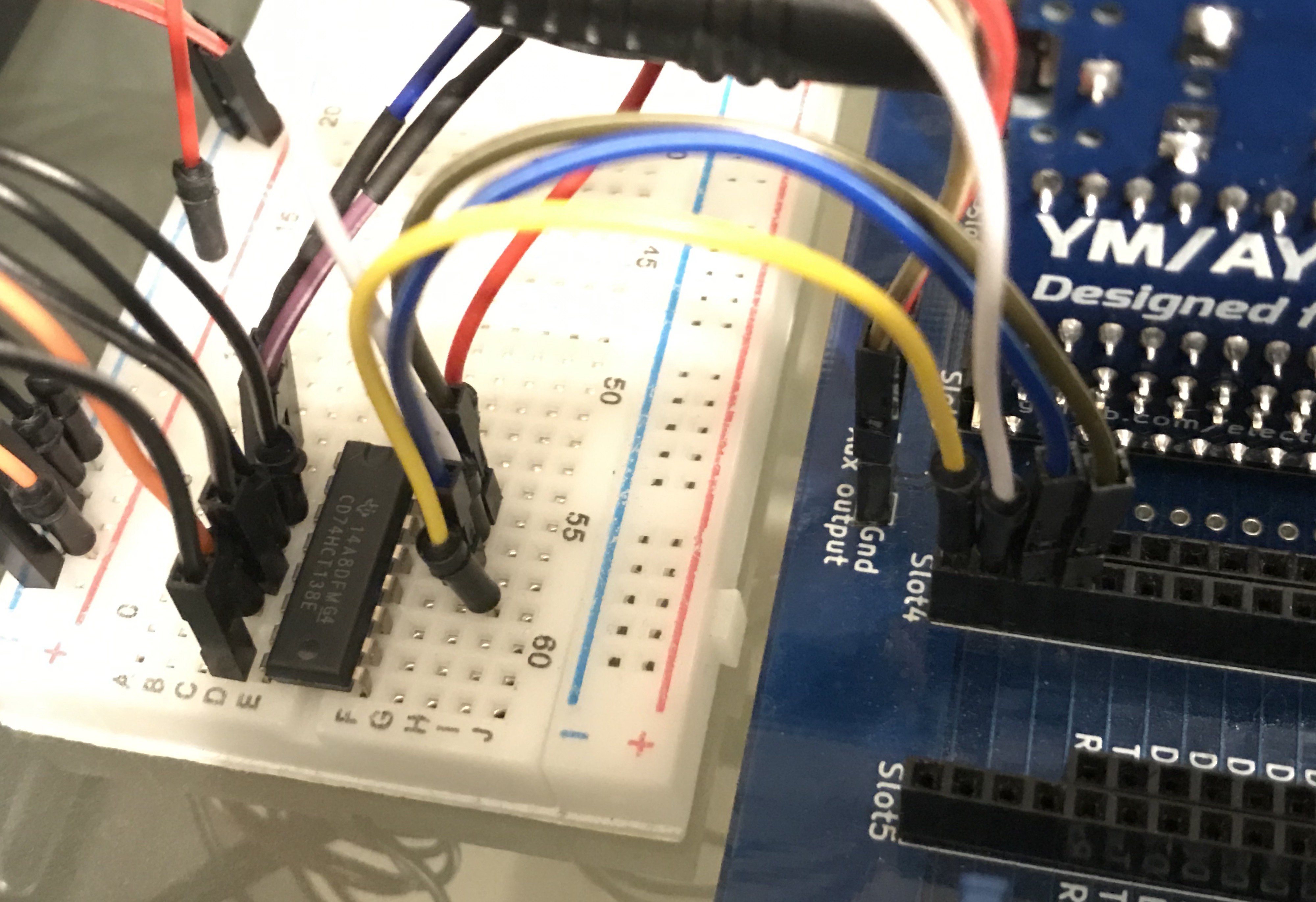
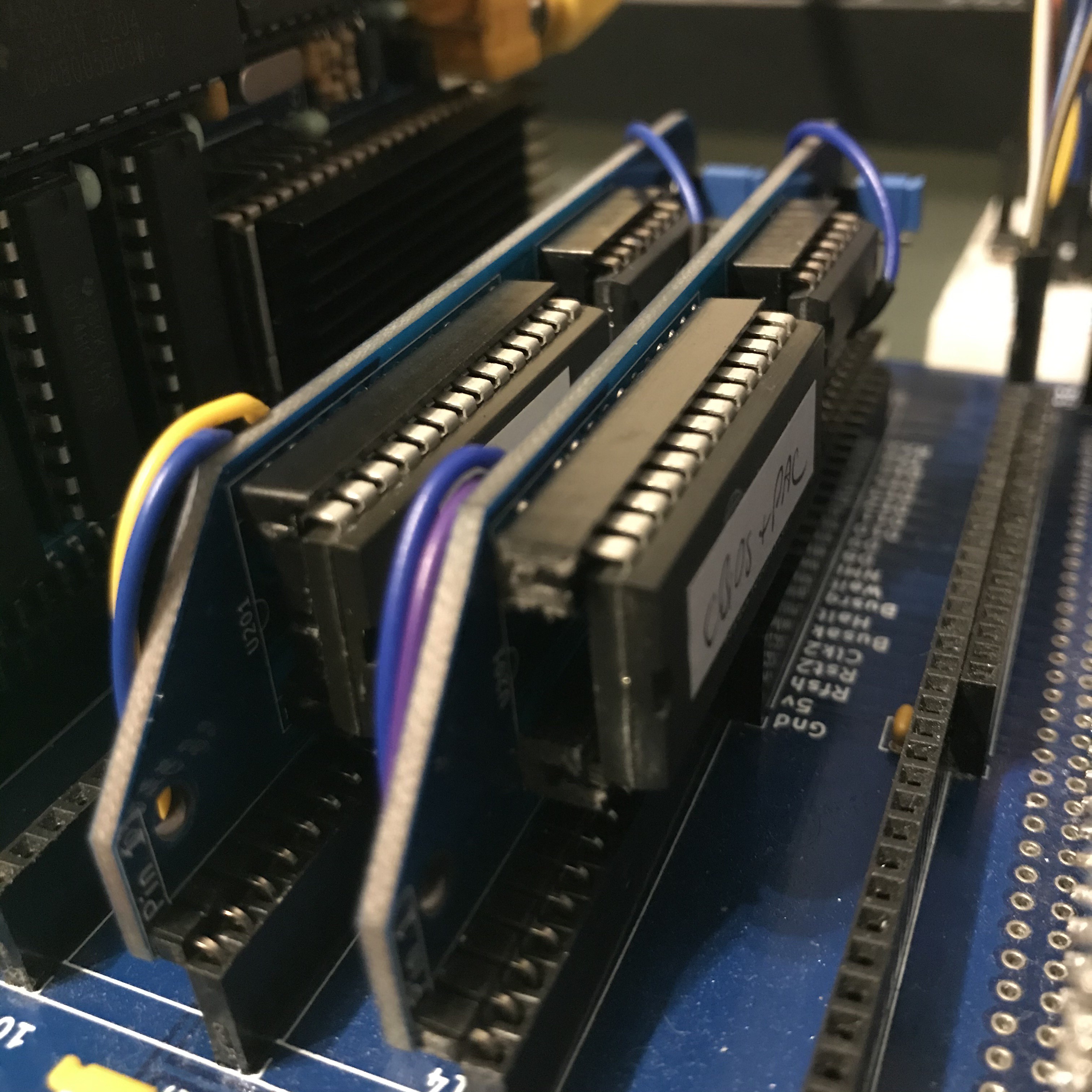
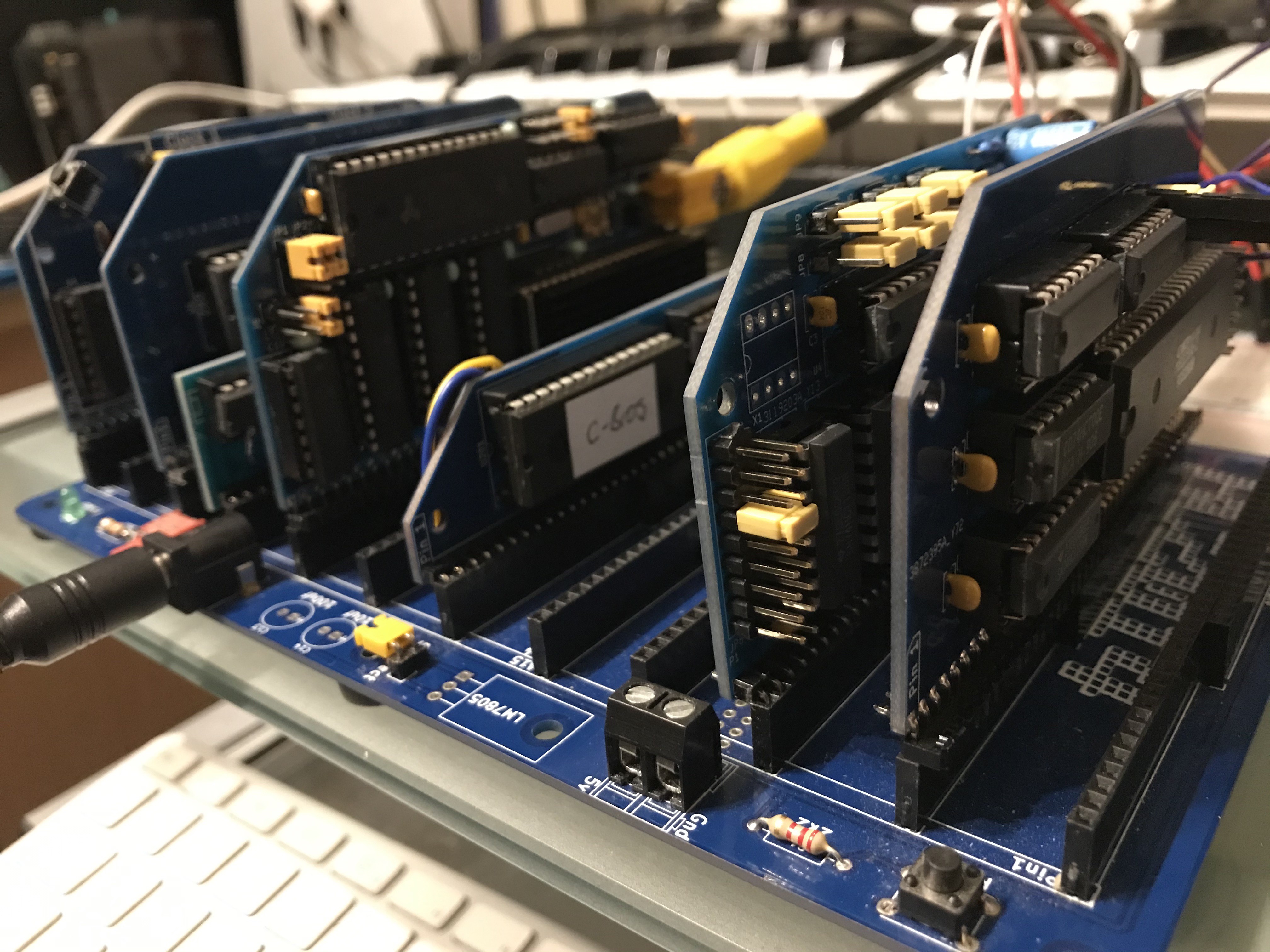
I'm using some standard RC2014 boards, it has been quite easy to bodge those so that they are enabled / disabled according to the appropriate slot selection line. Below are my two doctored ROM modules. One contains the BIOS, the other contains the cartridge ROM. They're hooked to different slot selection lines, and I've burned the cartridge ROM so that its data starts at $4000. (Later I'll come up with a hardware solution so that address $4000 selects address 0 of the chip - that will make burning the ROM chips easier.)
The RAM board is hidden in this picture but it looks similar to those two ROM boards. (ignore the label you can see on the rom chip, I've had to do a lot of experimentation and that's out of date.)
I had to do a lot of troubleshooting and experimentation. I wanted to use c-bios, partly because the code is open and partly because it's legit. However, I've only got this setup working today after trying the original MSX1+BASIC rom. In a way this is preferable because I want to be able to use BASIC and cassette loading, neither of which is available in c-bios yet.
So here's the machine working* with the original MSX rom - it shows some details before arriving here at the BASIC prompt. You can't see it in the static image, but it's flickering a lot as if an invisible hand is mashing my non-existent keys. I guess this is because of floating keyboard and joystick connections. (which will be the subjects of further logs in the not-too-distant future).
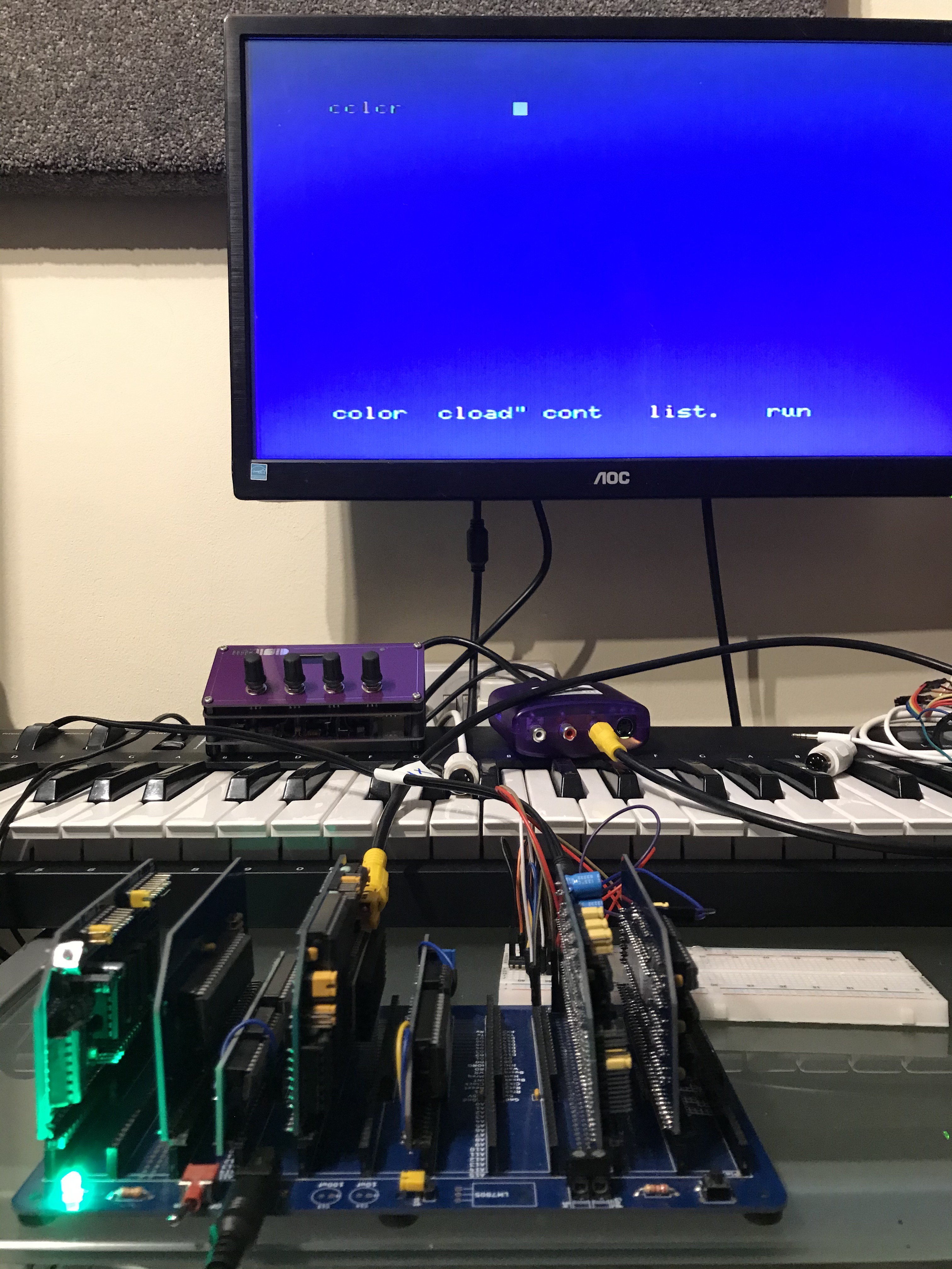
That's without a 'cartridge' module plugged in. Here's what happens with a 'cartridge module' in place (it's detected and run by the BIOS)
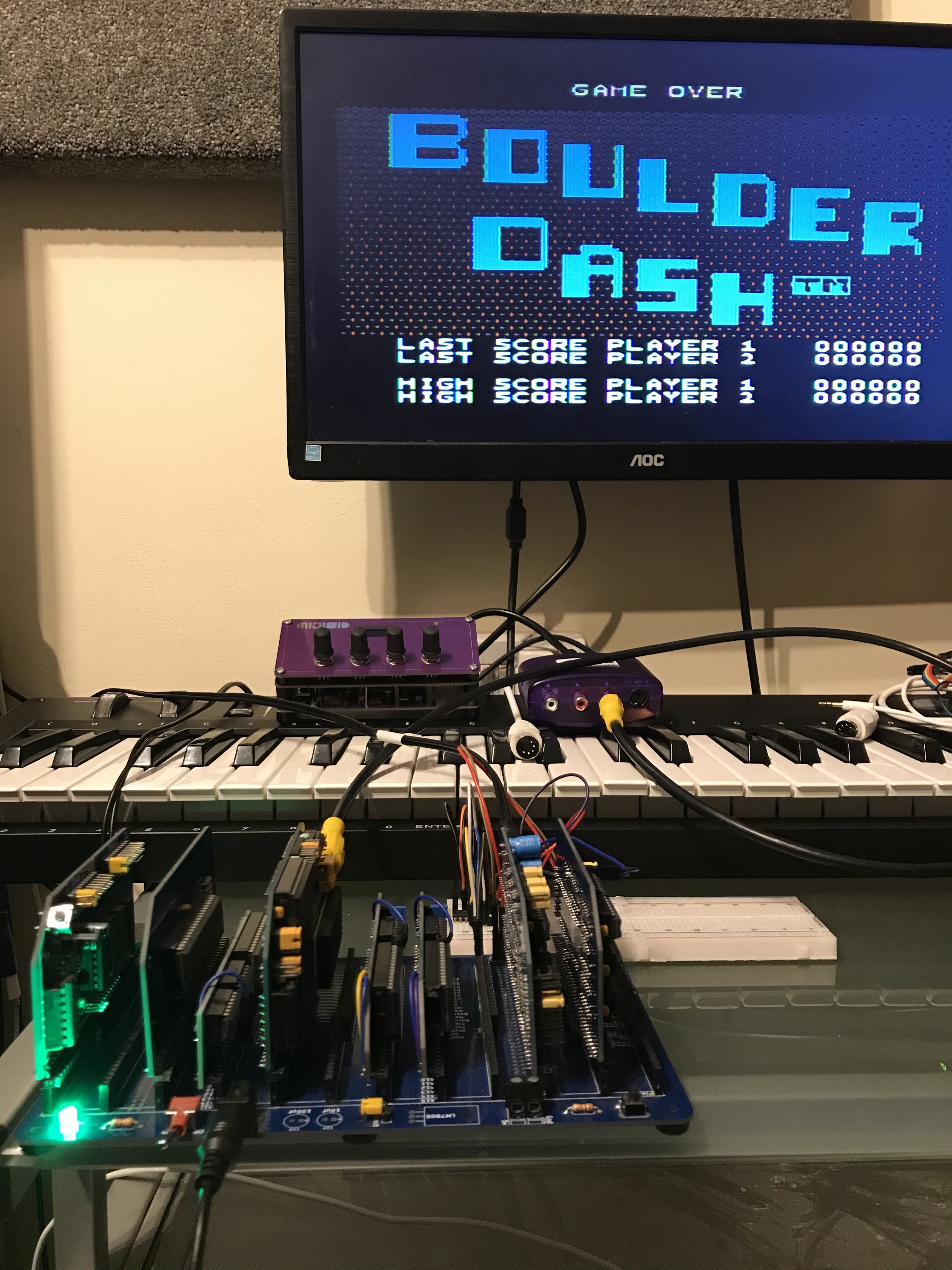
Again, it plays itself because of the invisible hand mashing keys / joystick but it's working* and there is sound.
So here's the system as it stands. I'm using an RC2014 Pro backplane because I need a lot of slots. I think this will all work with the standard RC2014 bus.
From front to back (the order that they're inserted isn't important):
- my PPI module (next job, make v2 of that),
- the Ed Brindley r6 YM/AY sound card
- 'cartridge module' which is a bodged RC2014 Classic ][ ROM board
- 'BIOS module' ditto
- the J B Langston TMS9918A module
- 'MSX ram module' which is a bodged RC2014 Classic RAM board
- Z80 CPU module - any one will do
- Clock module - I'm using my dual clock module so that I can jumper it to ~3Mhz
* working.... to a point. I can't use BASIC or play a game because I don't have a keyboard or joystick. Yet.
Discussions
Become a Hackaday.io Member
Create an account to leave a comment. Already have an account? Log In.