 Dr. Cockroach
After the adder was finished, I then decided to keep on going and the instruction decoder was next on my hit list. Not much in the number of images except for the final result. the left and bottom edges are the input buffers and inverters using npn transistors. The rest are AND gates using only diodes. This is the last build using thumb tacks on a wood base.

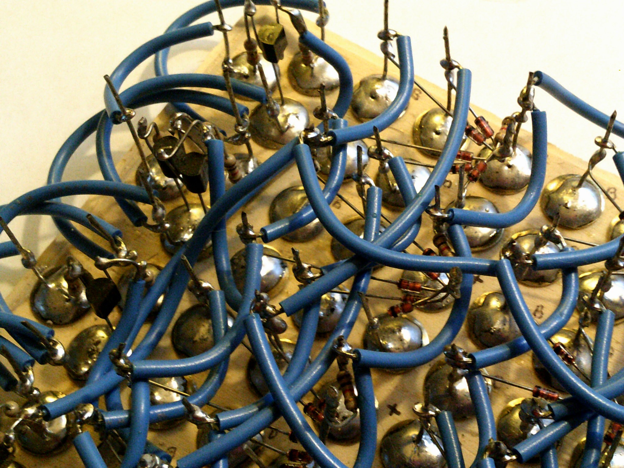
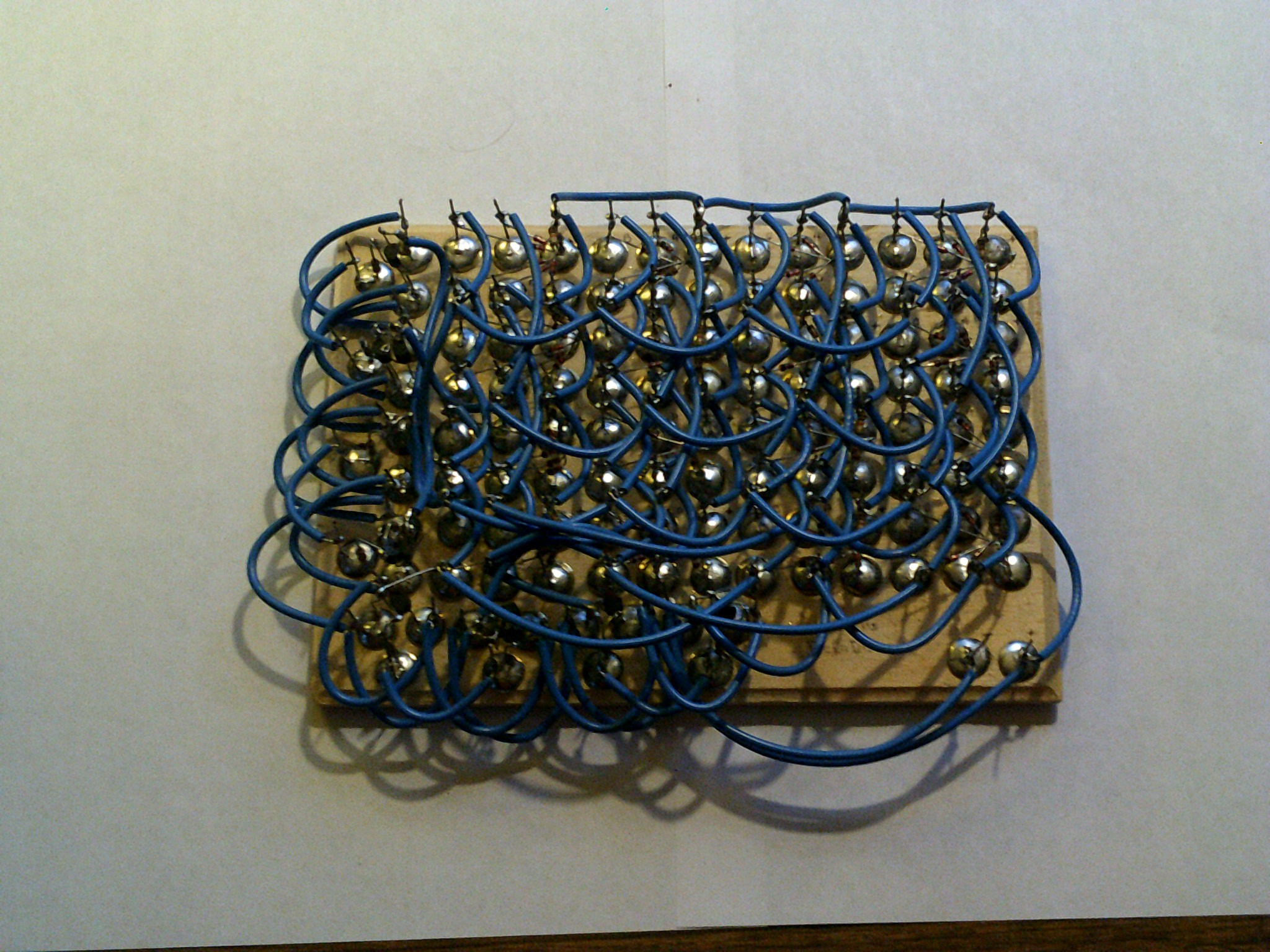
The close wiring on the decoder was a real headache but like the ALU, it worked without errors. ( well, one wrong transistor got mixed in )
Discussions
Become a Hackaday.io Member
Create an account to leave a comment. Already have an account? Log In.
Some people say I'm crazy.
I'll show them your work :-D
Are you sure? yes | no