 Dr. Cockroach
It is at last time to get cracking and work on the read logic for Brainwarp. The plan is to use my typical Nand / Not logic circuits and the following images should give everyone the idea of how much wiring this will take for reading up to 15 Brainwarp instructions. Remember that it will be one entire board for each card position on the Brainwarp panel.
This is the Logisim circuit that I will use.
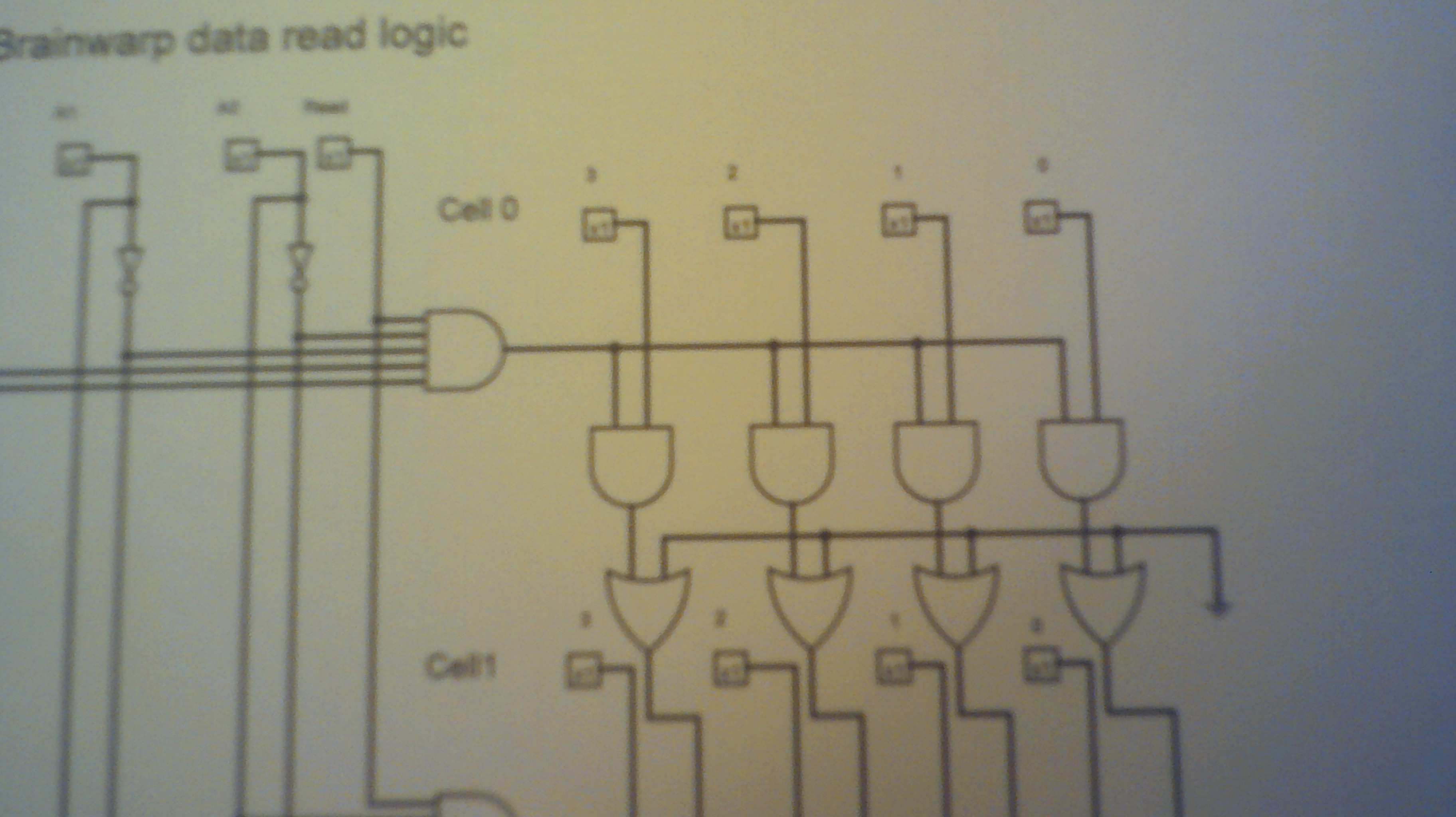
The board layout required for each of Brainwarps 15 instruction locations.
 This is the 5 input And gate using a Nand and Not gate. Led is the output side.
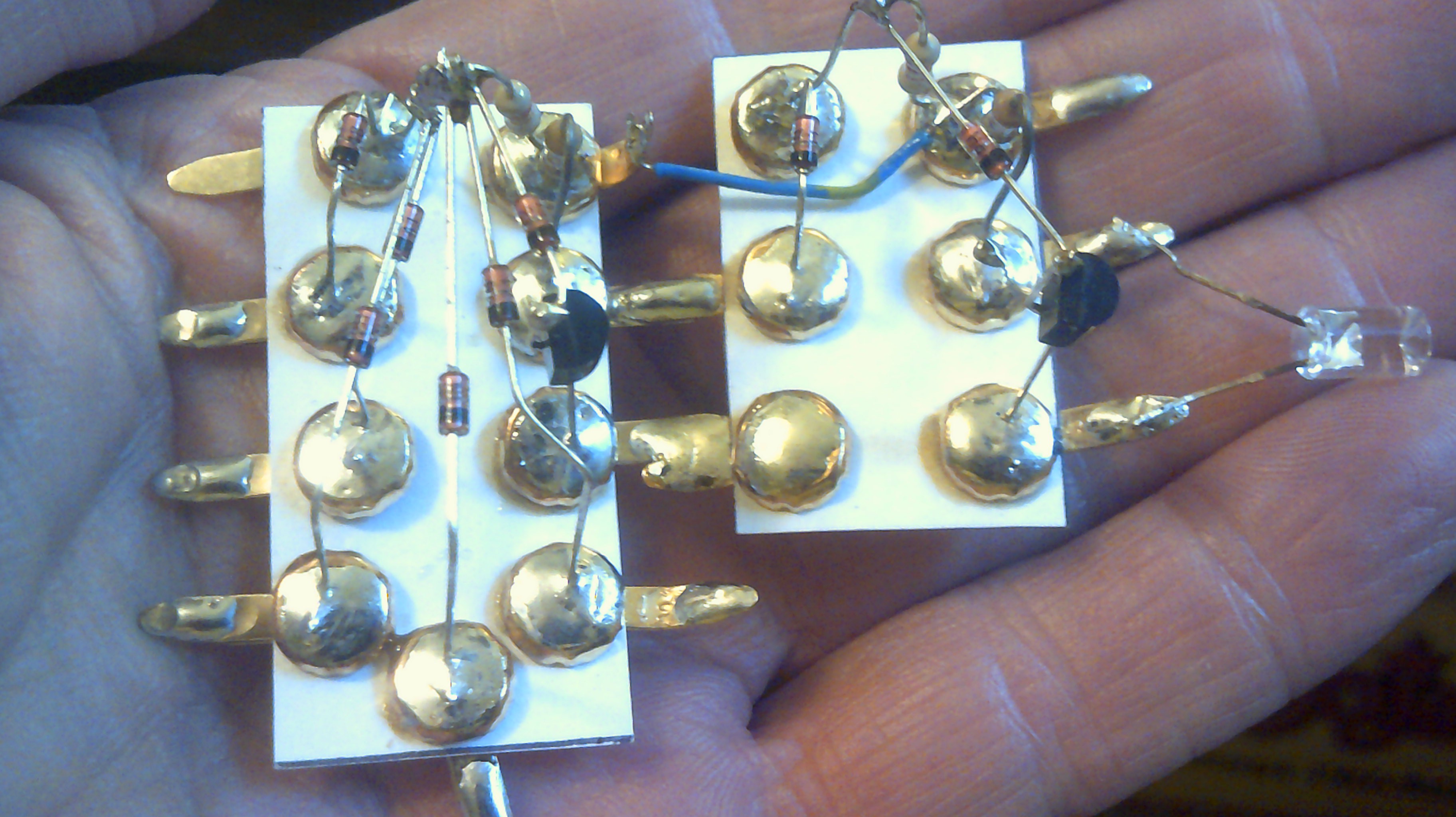
This how I can make And & Or gate modules. There is lots of room for improvement.

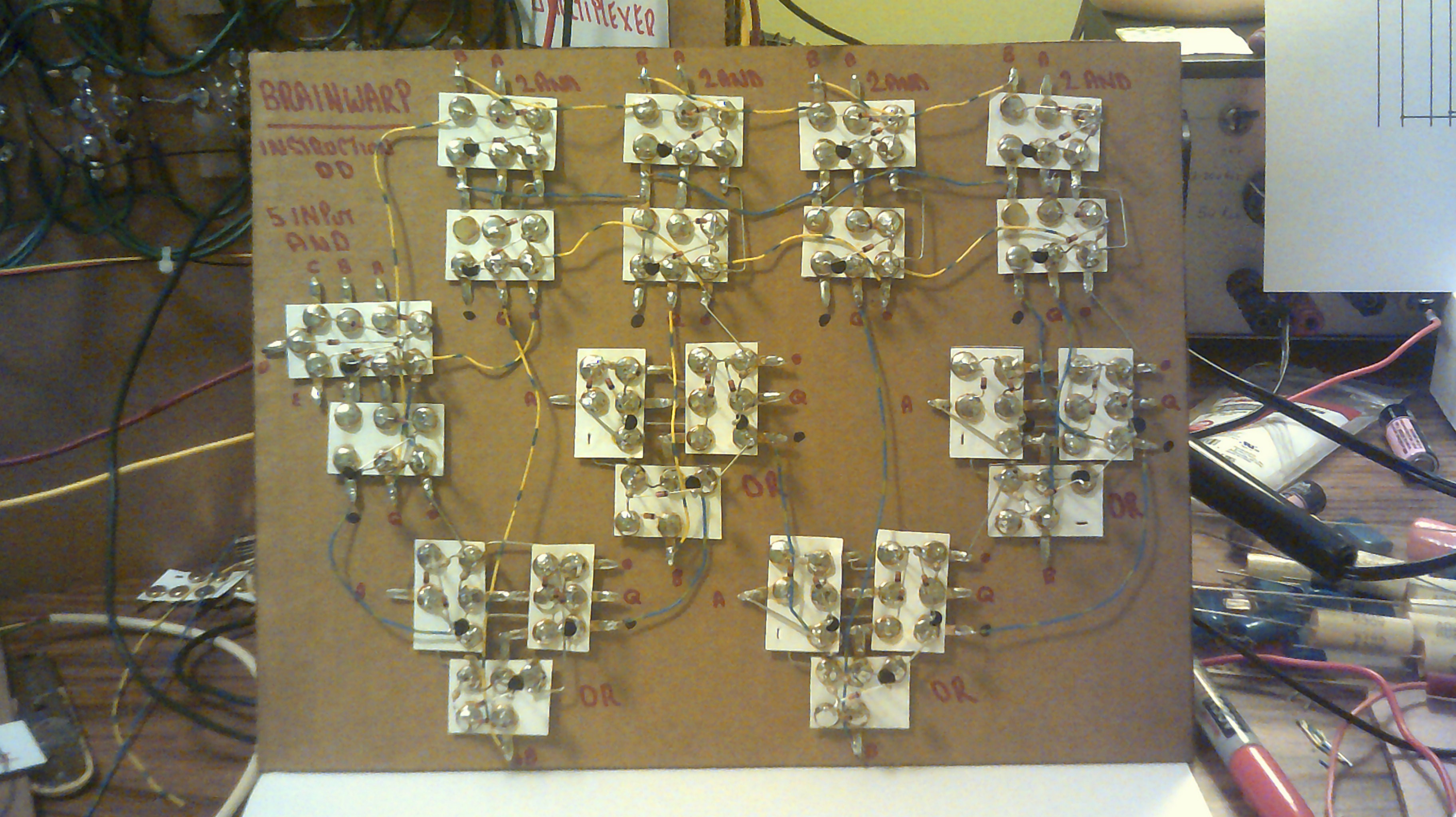
October 9, 2017 - The first Brainwarp read board with the logic gate modules glued down. Now to wire them up :-)

This is the wiring needed to read just one instruction on the panel.
Discussions
Become a Hackaday.io Member
Create an account to leave a comment. Already have an account? Log In.