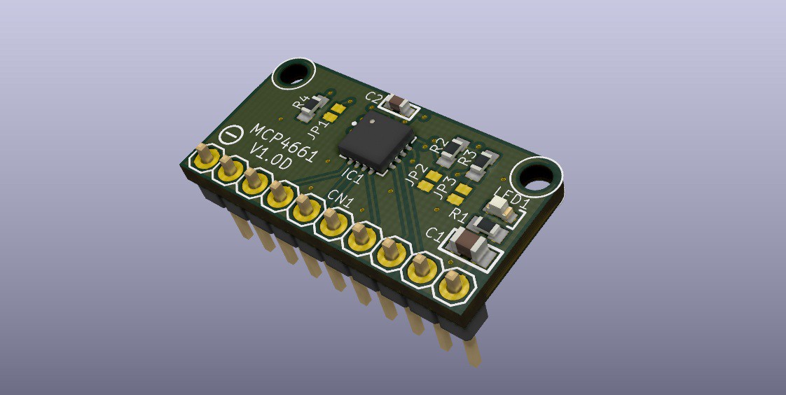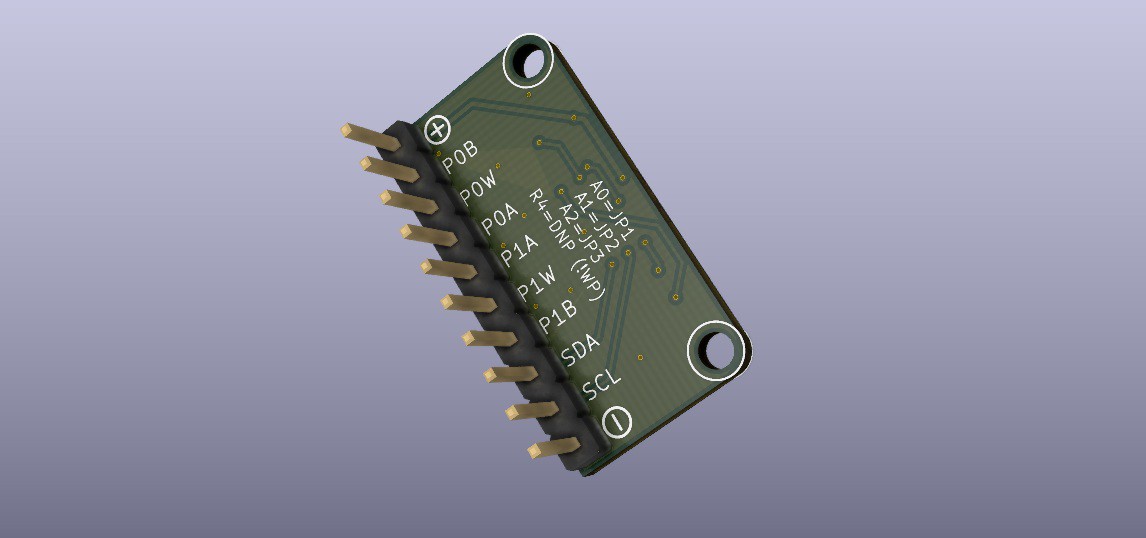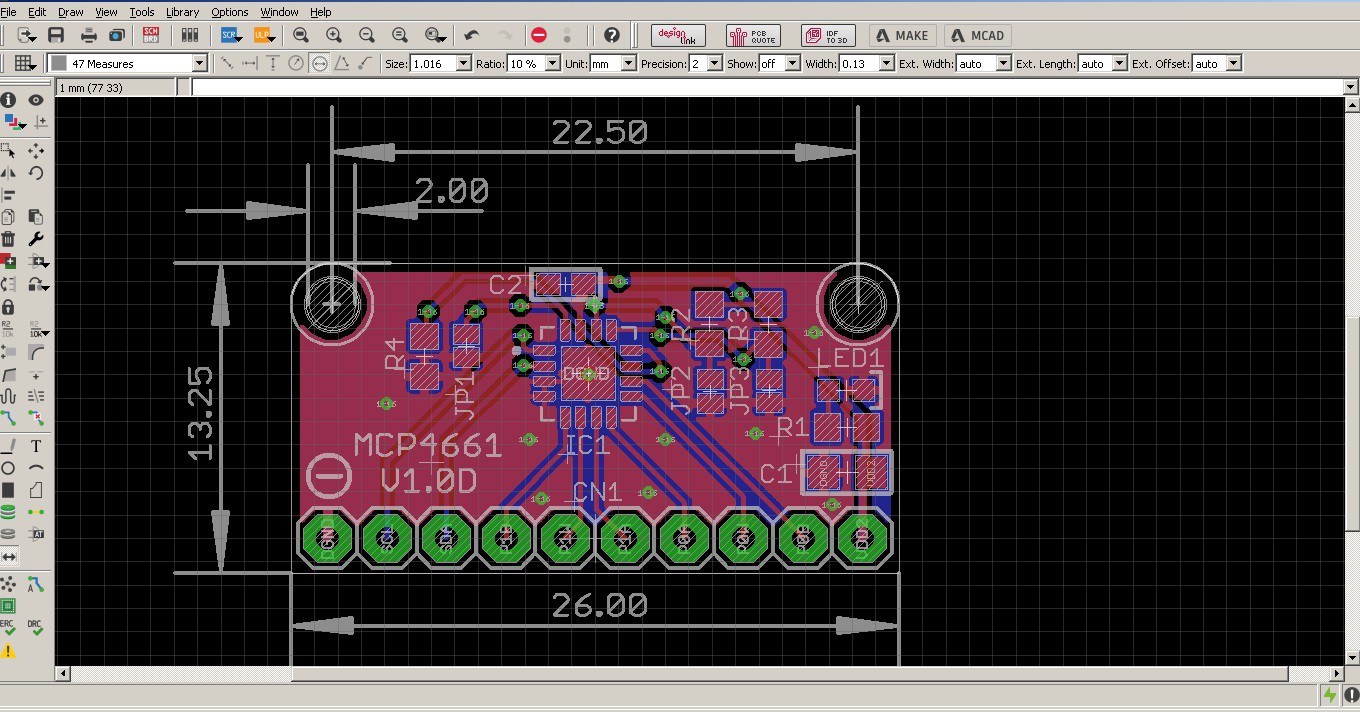

I made 4 different versions, here's a 3D model of one of them. There's QFN + TSSOP breakout versions, and then I made FPC + 2.54mm breakout versions.


--- DIGIPOT ---
These breakout PCBs have the built in jumpers for setting the I2C address - and, important note - the datasheet recommends A1, A2 be "non-static" that is, in a pulled high or low state. Power LED, decoupling caps, and a clean layout with some clear silk identifcation for pins is going to make these boards a winner. Soon to be very useful I think (when they arrive!) :)
--- FIRMWARE ---

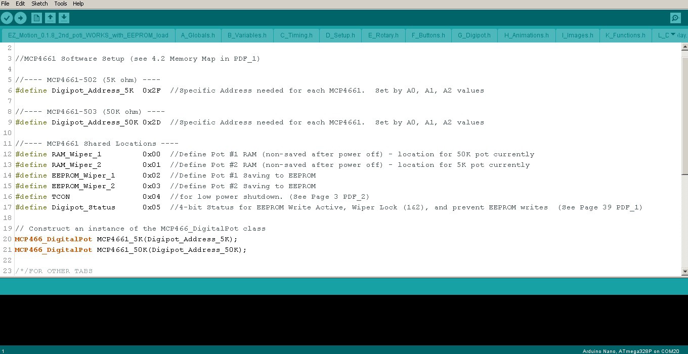
I also hit a new milestone in thefirmware today (yayyy) and got the 2nd digipot fully functional! It's a second IC with a different value (50K) to be used for controlling accelleration with the stock rheostat. I can't wait to try out some smoothed speed slopes with it. ^_^
Fortunately, I didn't have to dig into edits with the main library, and could get away with just the I2C address change (after using I2C scanner code, I found my digipots were 0x0D and 0x0F). However, my ported firmware needed to have a bunch of variables adjusted and renamed, display and menu updates, etc.
I also added some proper debouncing for the touch slider controls. Funny, it was accidentally "debounced" by the OLED display writes being slow on the same bus. Once I cleaned up the display with less text, the loop sped up *really* fast and killed off my fake debounce ;D so I wrote a bit of code for that and also added touch menu controls and multi-touch! More on that later :)
 CriptasticHacker
Discussions
Become a Hackaday.io Member
Create an account to leave a comment. Already have an account? Log In.