 CriptasticHacker
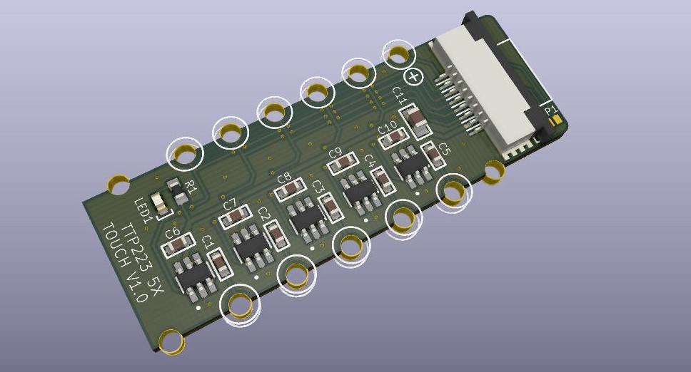
Spent the past 2x days creating new PCB designs... Took a while because I decided to tweak all my FPC libraries for improved accuracy and also had to create the TTP223 footprint from scratch for Eagle (really? yes, I was surprised this common part isn't available). At least the package is a common SOT-23-6L.
It's worth noting that this smaller package for the TTP223 (there's a much larger one in SSOP-16 package) loses some features. It does not support:
1) Power on reset
2) Open drain output (a.k.a. hi-Z)
3) The press time is fixed at ~1.6ms
4) Doesn't have maximum on time (100 sec)
None of these are a significant loss though, so I think we're still in good shape.
we have here a 3D mockup of my 5X TTP223 touch PCB - specifically designed as a solder mount for my new slider PCB.
I think this slider design should work well, but just to be safe I made a 3X version as well for shorter finger travel distances.
Disregard the silk and vias outside the board perimeter - these are edge castellations, but KiCAD 3D modeling doesn't know how to interpret them.
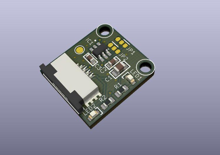
I also went ahead and designed a standalone version, since the cheapo models around the internet usually don't have:
1) Mounting holes
2) FFC connectors
3) Proper isolation of the projective capacitance pin
4) A footprint to tweak the projective capacitance (0-50pf variable cap is in the TTP223 datasheet).
Alright, I think I'm all set for capcitive touch stuff! Next is onto breakout PCBs and magnet stuff :)
[more coming soon...]
Discussions
Become a Hackaday.io Member
Create an account to leave a comment. Already have an account? Log In.