 CriptasticHacker
-- UI OLED Rotary PCB --
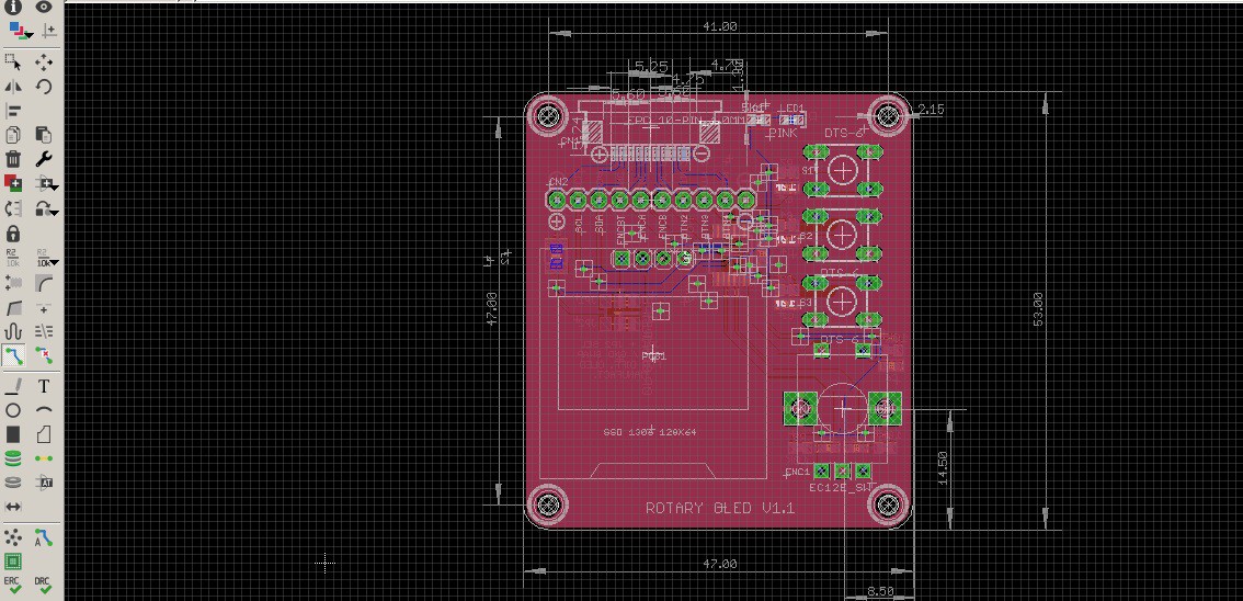
I also went ahead and made an ugpraded UI PCB:
False positives from janky breadboard rotary pushes were getting on my nerves...
This handsome lad has multi hardware debouncing, and expands our setup to 4x push buttons :) Everything is incredibly responsive on the interrupts and much more durable. Now we need a bottom case to protecc it....
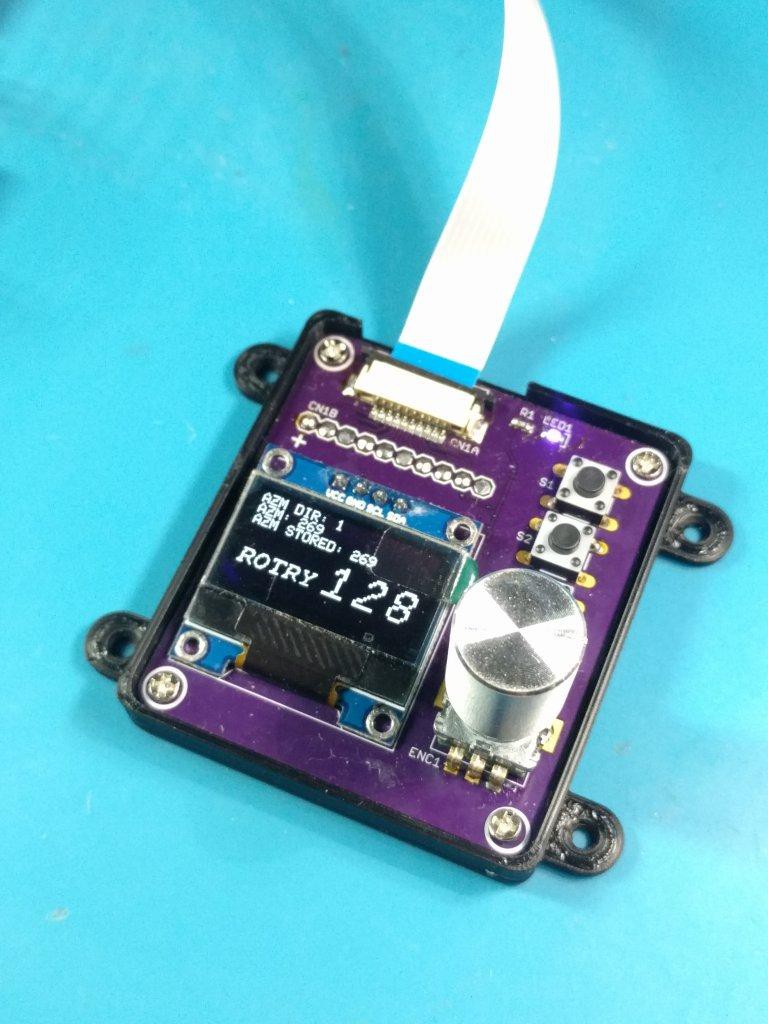
This is V0.2 which has a support for those hard-presses on the rotary encoder, plus reinforced corner screw standoffs :)
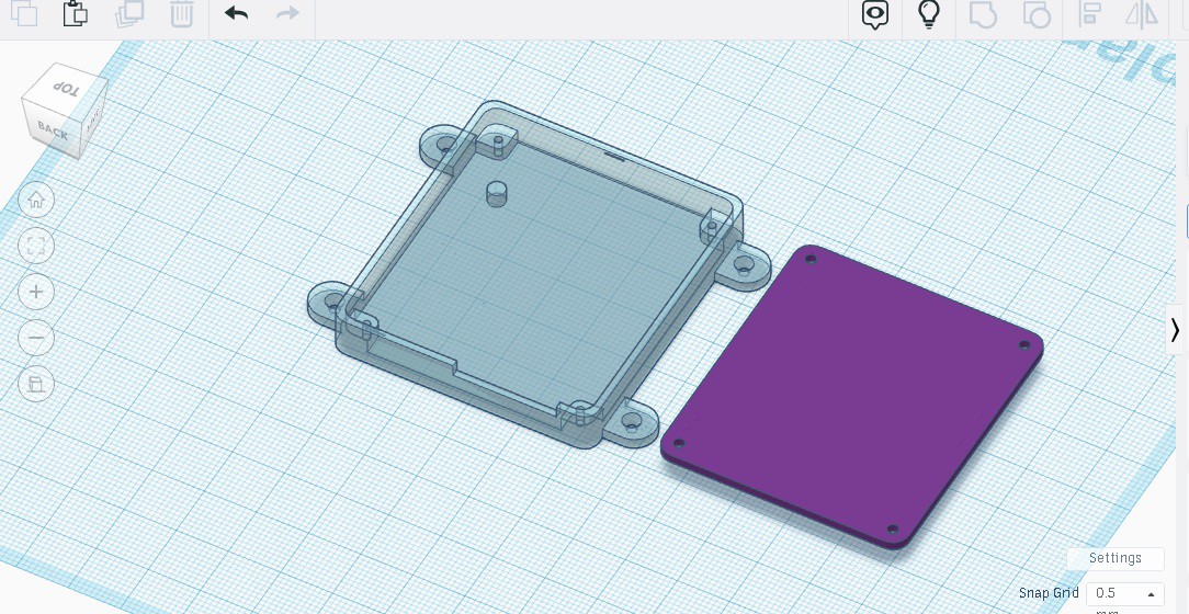
Time to print!
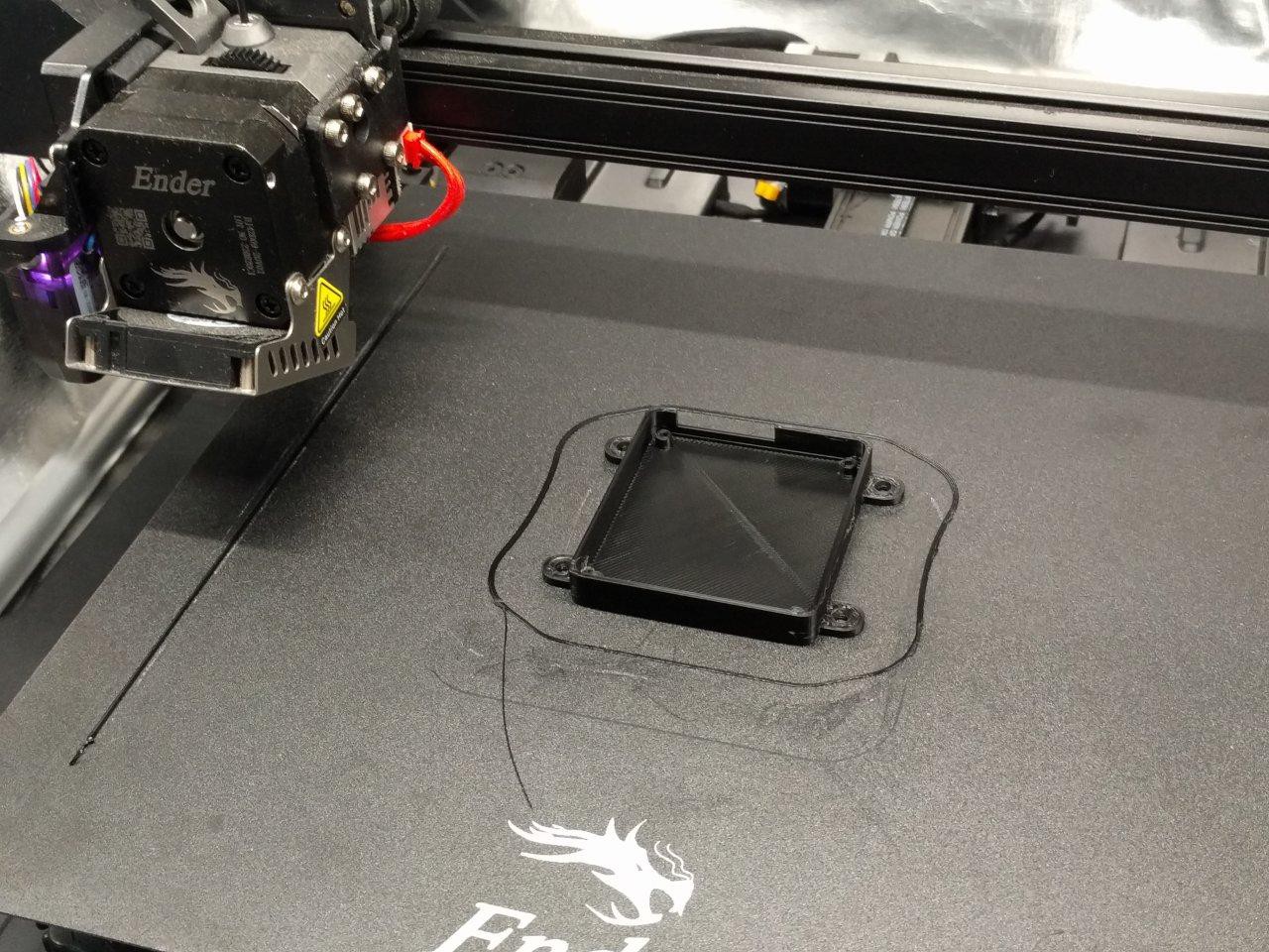
Looks spiffy - but does it fit? I always hold my breath for this part...
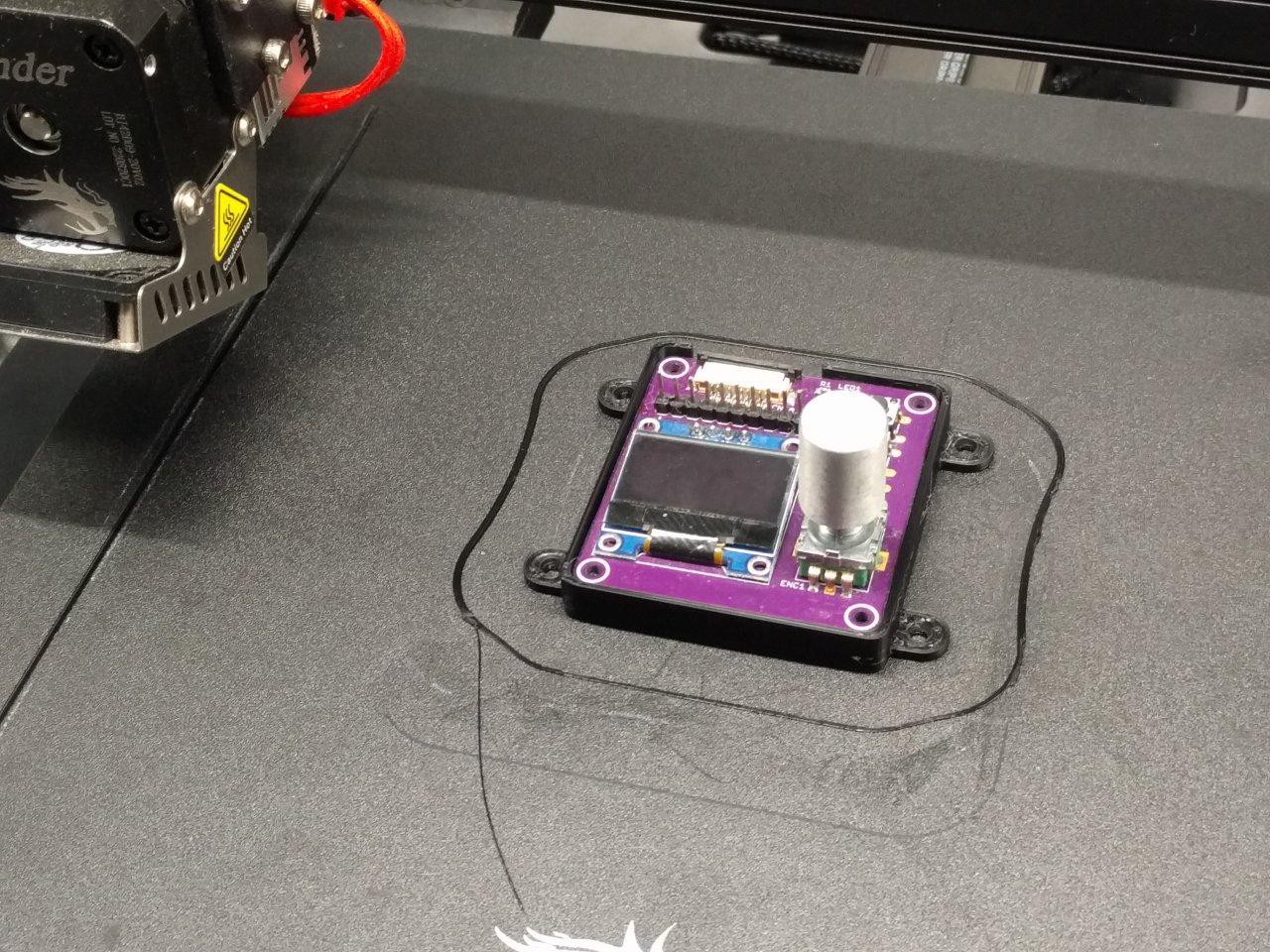
Success! And one more close of shot of the handsome chap:
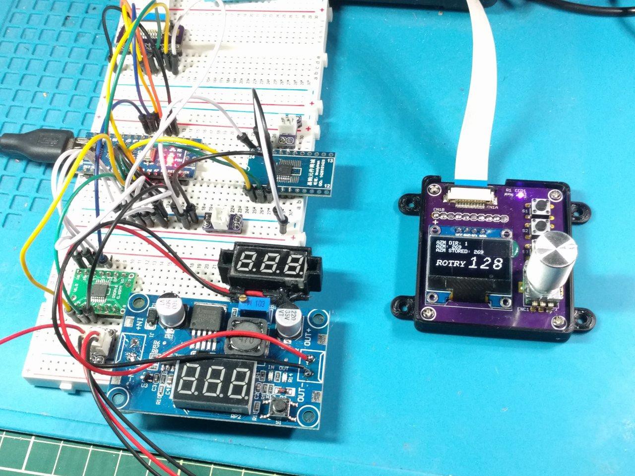
Looking more and more like a real test rig!
[to be continued...]
Discussions
Become a Hackaday.io Member
Create an account to leave a comment. Already have an account? Log In.