PCB
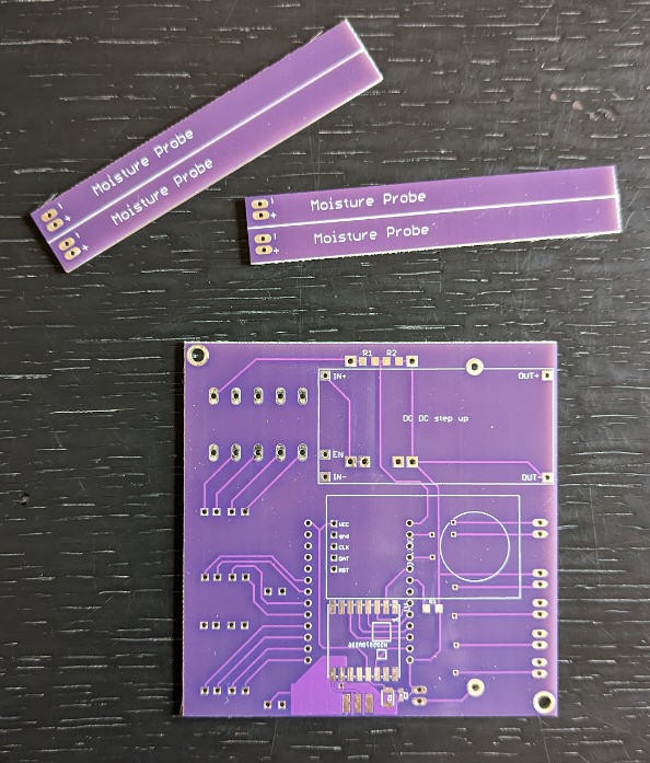
PCBWay kindly offerred to sponsor this project and manufactured the Rezodo PCB.

The PCB is a beautiful dual sides board. Manufacturing is simply perfect. The boards came with four soil moistures probes that you can detach easily.
Here is a small video explaining how you can design PCBs with "Vcuts" as I did to "panelize the PCB" for the moisture probes :
Soldering the board
Soldering the board is a piece of cake, start by the lora module and the smd resistors and capacitors.
Then solder each module using pins and finish with the big terminal blocks and the battery holder.
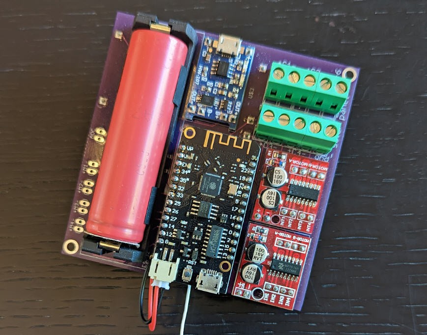
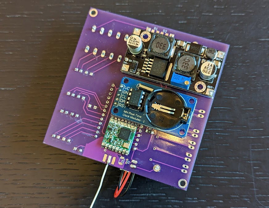
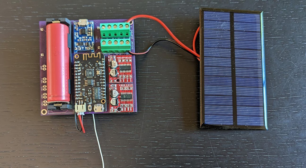
The solar panel connects on the right side of the terminal blocks. Respect the polarities .... Inversion would destroy the board... Same advice applies when inserting the battery into its holder: respect the polarities.
Voltage booster
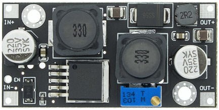
The XL6019 step up converter is equiped with an "enable" pin to shut it down when not used. R3 resistor on the board must be soldered to pull down the enable pin even when the ESP32 is sleeping. This will insure a low power consumption...
It has also a trim potentiometer to tune the output voltage. Do not forget to tune the output to the right value for your irrigation valves...
Lora antenna
Do not forget to solder the antenna for the lora module if you don't want to fry the RF stage...
Antenna could be either a SMA connector and a pigtail antenna, or a simple wire (see picture white wire).
If you choose the wire option be sure to cut a piece of wire at the exact dimension of 1/4 wave to have a monopole antenna.
- For 868MHz wavelength is 34.538cm. Thus our antenna must have 8.63cm length.
- For 915MHz wavelength is 32.764cm. Thus our antenna must have 8.191cm length.
Beware that LoRa transmits over license-free megahertz radio frequency bands: 169 MHz, 433 MHz (Asia), 868 MHz (Europe) and 915 MHz (North America).
Adapt the length of your antenna to the frequency of your module.
You can build more efficient antenna.... here is one I designed 5 years ago : dipole 868MHz antenna
Powering the device
Rezodo device is intended to be powered by the solar panel and the 18650 Li-ion battery.
The charger (blue board on the right side of the battery) is equiped with a USB plug which can be used to charge the battery in complement of the solar panel. You can safely power the device with this USB connector.
The ESP32 must be connected to the board using a small pin header into the battery port.
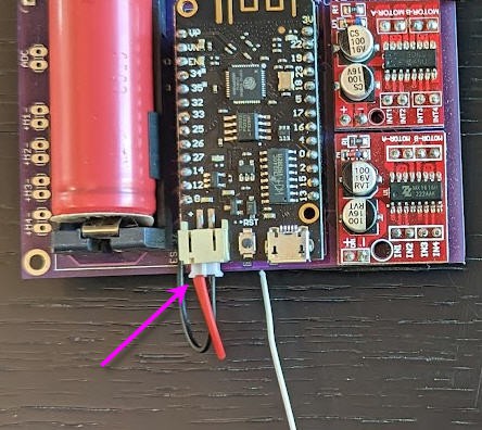
The USB connector ot he ESP32 should only be used to connect USB serial to flash new firmware or to debug the software. When you plug this USB socket, please do not connect another USB plug into the charger connector...
Connecting the irrigation valves
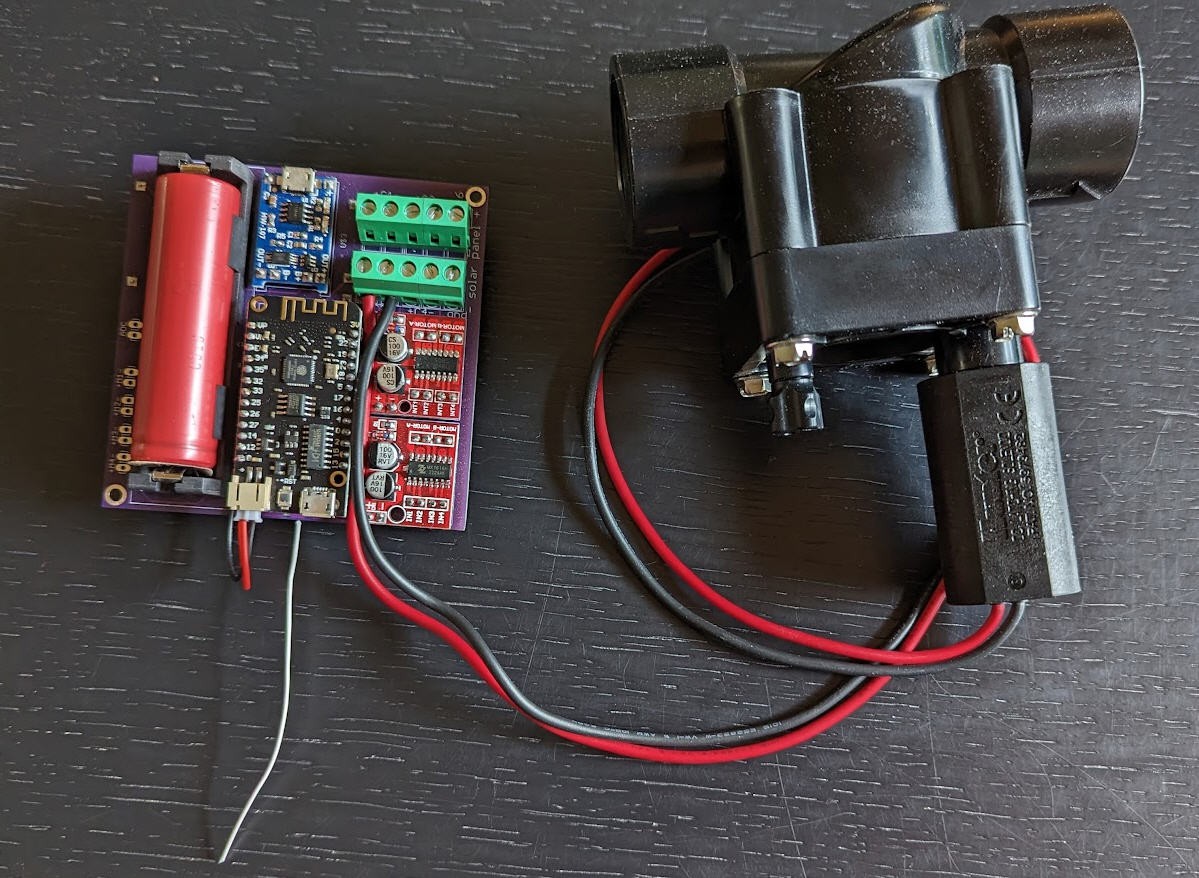
The valves connect on the terminal block marked C1 to C4
As an example, here is the coil C3 connected to a valve. (respect the polarilty... if not, closing the valve will open the tap !)
Various configurations for your Rezodo devices
Fully functionnal board
The most powerful configuration includes all the components of the board
- solar panel
- charger
- battery
- voltage booster
- motor/coils drivers
- lora + antenna
- ESP32 and ESPNow
- real time clock
board without lora
if you don't need lora, simply do not solder the lora module and the antenna
board with less coil drivers
if you only need to power one or two coils, a single driver will be enough.
board without any coil driver
if you don't need to control irrigation, then don not solder the two drivers nor the voltage booster
board without real time clock
Although not recommended, the ESP32 board is also equiped with and internal RTC. This RTC has a lot of daily drift... Time synchronization could suffer a little, but the software handles this situation. You can if you want avoid to solder RTC module (not recommended)
 JP Gleyzes
Discussions
Become a Hackaday.io Member
Create an account to leave a comment. Already have an account? Log In.