-
The FDRS Library and my modifications
04/16/2023 at 10:11 • 0 commentsWhy did I need to modify FDRS ?
In FDRS library, Devices are classified into two types: Gateways and Nodes.
- Gateways comprise the infrastructure of the network, moving data along pre-directed routes and providing coverage to all devices.
- Nodes allow the user to exchange data with a gateway.
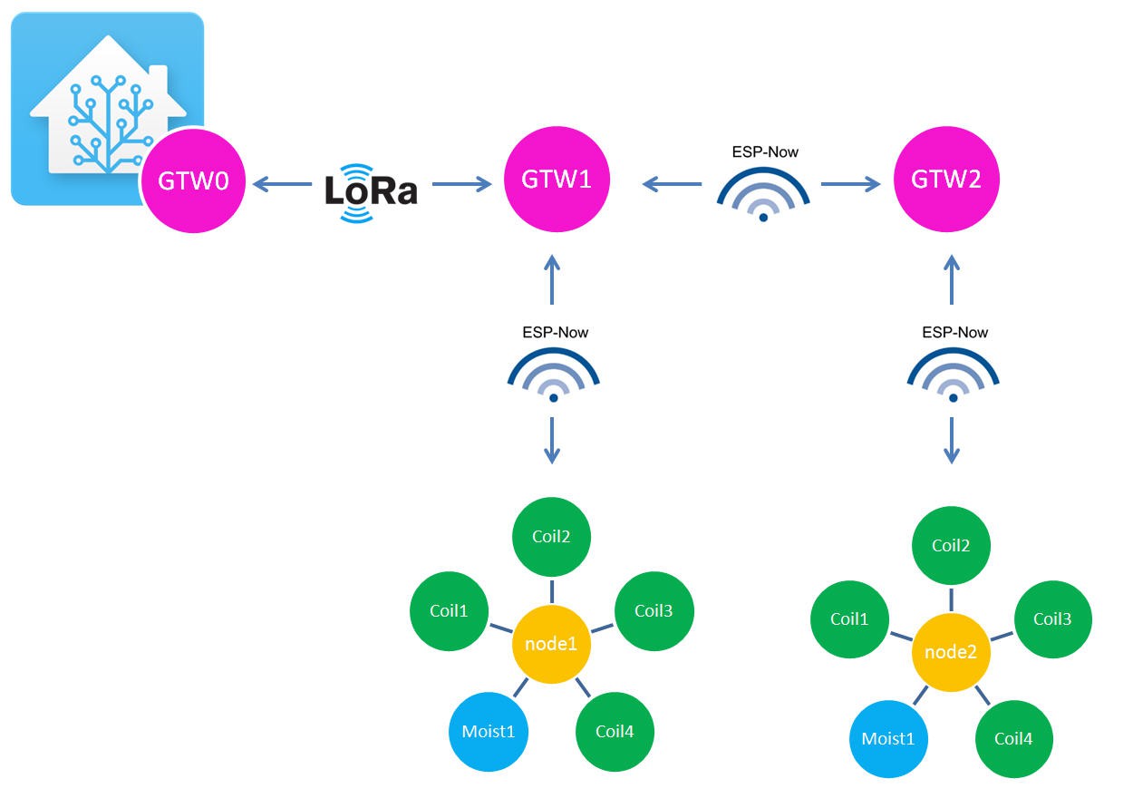
Gateways and nodes are physically independant devices. Thus for a simple 3 devices Rezodo network I would have to deploy 5 devices if working with genuine FDRS library.
![]()
I discussed a lot with Timm and understood his motivations to stay with his concept (gateways/nodes). But as I had already manufactured my boards, I decided to modify FDRS to open a little its API for a Gateway to be both acting as gateway and node.
![]() Timm is currently reviewing my modifications and will decide to merge them(or not!) into FDRS master.
Timm is currently reviewing my modifications and will decide to merge them(or not!) into FDRS master.Meanwhile we will try to enter (a little) into FDRS inner working.
FDRS inner working
Bear in mind that I will not at all cover the explaination of "FDRS nodes" as I will not use them with my mods...
However you should start to read the very good documentation writen by Timm:
As I will mostly use the networking layer of FDRS it is important to understand of it works.
FDRS is internally exchanging binary messages which are arrays of "dataReadings"
typedef struct __attribute__((packed)) DataReading {
  float d;
  uint16_t id;
  uint8_t t;
} DataReading;
As such messages include:
- the data payload (d) as a 32bits float number
- the identifier (id) as a 16 bits unsigned integer number
- the type (t) as a 8 bits unsigned integer
A single message is addressed by gateways to any node willing to get this id message.
Routing message from gateway to gateway will be explained later. But for now remember that a gateway has a unique "MAC address" which is a 8 bits integer number.
In the current implementation of FDRS it is not possible to address a control message to a gateway.
My modification will try to perform this task without damaging the FDRS library has it is today.
I adopted the following conventions which are important to follow for my mods to work:
- the master gateway will always have the address 0,
// GATEWAY CONFIGURATION //Addresses #define UNIT_MAC 0x00 // The address of this gateway- control messages will go from this gateway GTW0 to the others "down to the right one" (example "open valve 1 on GTW2")
- sensor data will go up from the gateways to the GTW0 and then to IoT platforms (explained later)
To allow extra behavior of FDRS I have modified the library to expose messages into the user writen code of the gateway.
//FDRS
#include "fdrs_gateway_config.h"  //https://github.com/timmbogner/Farm-Data-Relay-System
#include <fdrs_gateway.h>
extern DataReading myCtrlData[256];
extern uint8_t myCtrl;
As you can see extern variables are now accessible containing myCtrlData array of messages (dataReading type). The myCtrl variable gives the number of received messages to be read.
To allow identifying the destinee gateway for a CtrlMessage, I simply use half of the id (high byte) to pass the GTW MAC address and the low byte to pass the message id.
so if you want to send a message to GTW 2 with a Ctrl_id of 3 you will write something similar to
  uint8_t GTW =2;
  unint8_t Ctrl_id = 3;
  uint16_t id;
  unint8_t t = 255;
  id = (GTW << 8) + Ctrl_id;
  float data = 333.0;
  //loadFDRS(float data, uint8_t type, uint16_t id);
  loadFDRS(data, t, id); //will load message into FDRS
  sendFDRS();            //send data using INTERNAL_ACT event.
And when the message will arrive at destination you will have to read it into a loop and trigger relevant action:
if (myCtrl > 0) //we have received at least a control message for this gateway { for (int i = 0 ; i < myCtrl; i++) //for each control message { int id = myCtrlData[i].id >> 8; //extract the GTW id int index = myCtrlData[i].id & 0xFF; //extract the Control Identifier myCtrlData[i].id = 0x8000; //reset the id to unused value (eat the message) if (id == UNIT_MAC) // if the message is for this gateway { switch (index) { case 1: //do something with type and data DBG(myCtrlData[i].t); DBG(myCtrlData[i].d); break; } } myCtrl = 0; //reset the message counter } -
Rezodo PCB assembly
04/13/2023 at 20:49 • 0 commentsPCB
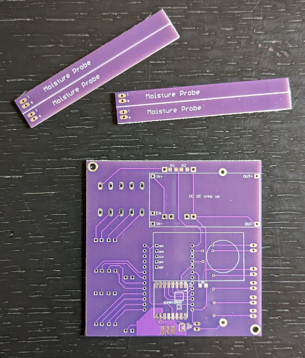
PCBWay kindly offerred to sponsor this project and manufactured the Rezodo PCB.
![]()
The PCB is a beautiful dual sides board. Manufacturing is simply perfect. The boards came with four soil moistures probes that you can detach easily.
![]()
Here is a small video explaining how you can design PCBs with "Vcuts" as I did to "panelize the PCB" for the moisture probes :
Soldering the board
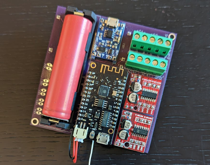
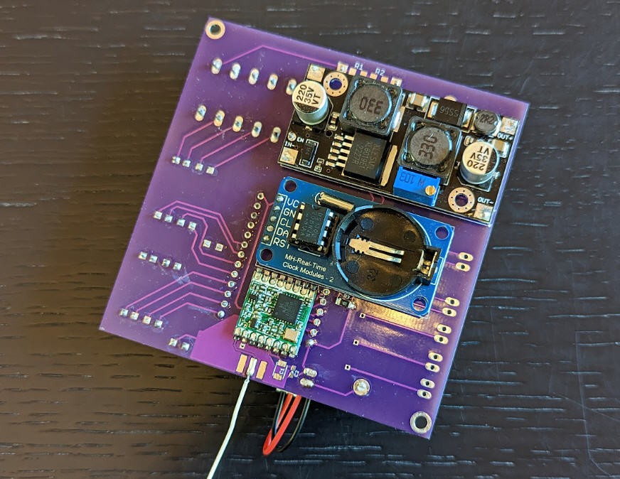
Soldering the board is a piece of cake, start by the lora module and the smd resistors and capacitors.
Then solder each module using pins and finish with the big terminal blocks and the battery holder.
![]()
![]()
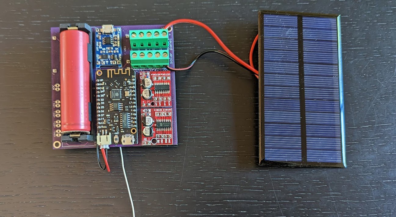
The solar panel connects on the right side of the terminal blocks. Respect the polarities .... Inversion would destroy the board... Same advice applies when inserting the battery into its holder: respect the polarities.
![]()
Voltage booster
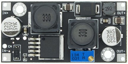
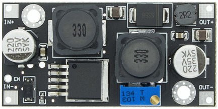
The XL6019 step up converter is equiped with an "enable" pin to shut it down when not used. R3 resistor on the board must be soldered to pull down the enable pin even when the ESP32 is sleeping. This will insure a low power consumption...
It has also a trim potentiometer to tune the output voltage. Do not forget to tune the output to the right value for your irrigation valves...
![]()
Lora antenna
Do not forget to solder the antenna for the lora module if you don't want to fry the RF stage...
Antenna could be either a SMA connector and a pigtail antenna, or a simple wire (see picture white wire).
If you choose the wire option be sure to cut a piece of wire at the exact dimension of 1/4 wave to have a monopole antenna.
- For 868MHz wavelength is 34.538cm. Thus our antenna must have 8.63cm length.
- For 915MHz wavelength is 32.764cm. Thus our antenna must have 8.191cm length.
Beware that LoRa transmits over license-free megahertz radio frequency bands: 169 MHz, 433 MHz (Asia), 868 MHz (Europe) and 915 MHz (North America).
Adapt the length of your antenna to the frequency of your module.
You can build more efficient antenna.... here is one I designed 5 years ago : dipole 868MHz antenna
Powering the device
Rezodo device is intended to be powered by the solar panel and the 18650 Li-ion battery.
The charger (blue board on the right side of the battery) is equiped with a USB plug which can be used to charge the battery in complement of the solar panel. You can safely power the device with this USB connector.
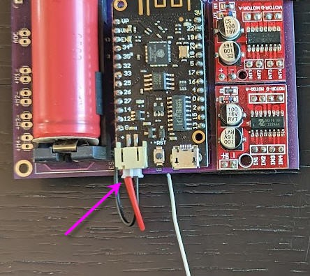
The ESP32 must be connected to the board using a small pin header into the battery port.
![]()
The USB connector ot he ESP32 should only be used to connect USB serial to flash new firmware or to debug the software. When you plug this USB socket, please do not connect another USB plug into the charger connector...
Connecting the irrigation valves
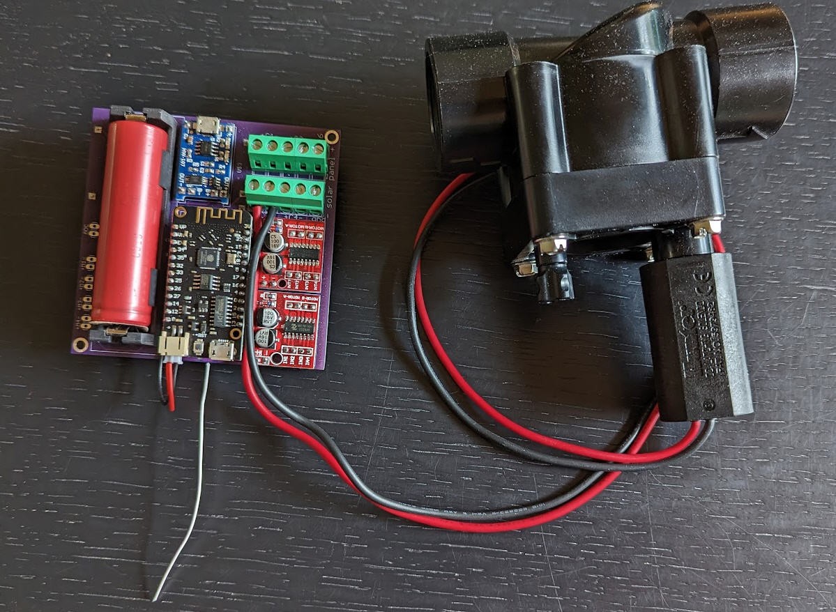
The valves connect on the terminal block marked C1 to C4
As an example, here is the coil C3 connected to a valve. (respect the polarilty... if not, closing the valve will open the tap !)
![]()
Various configurations for your Rezodo devices
Fully functionnal board
The most powerful configuration includes all the components of the board
- solar panel
- charger
- battery
- voltage booster
- motor/coils drivers
- lora + antenna
- ESP32 and ESPNow
- real time clock
board without lora
if you don't need lora, simply do not solder the lora module and the antenna
board with less coil drivers
if you only need to power one or two coils, a single driver will be enough.
board without any coil driver
if you don't need to control irrigation, then don not solder the two drivers nor the voltage booster
board without real time clock
Although not recommended, the ESP32 board is also equiped with and internal RTC. This RTC has a lot of daily drift... Time synchronization could suffer a little, but the software handles this situation. You can if you want avoid to solder RTC module (not recommended)
-
Rezodo device schematics
04/13/2023 at 20:46 • 0 commentsSome explainations on Rezodo schematics
Electrovalve choice
Our Rezodo will be a "low energy" system which must be powered by a small solar panel.
This is a key driver for the choice of electrovalves for the irrigation system.
Irrigation could last for hours during which the electrovalve must remain at the "open state". If we choose a simple coil which must be energized during the whole irrigation cycle, the battery would drain quite fast.
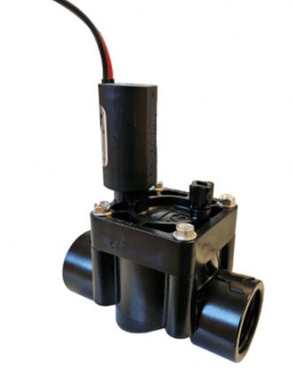
By chance, Hunter proposes 9V solenoids with a latching mechanism.
- you apply power to the coil, the valve opens and remains opened even if no more power is applied
- you switch the polarity and apply another pulse and the valve closes
So this type of latching electrovalve is mandatory for low power devices.
![]()
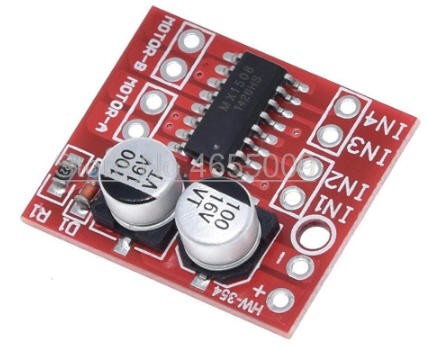
The elctrovalve will be driven by a little DC motor driver
![]()
One driver being able to drive two motors or in our application two electrovalves.
The electrovalve needs 9V DC to energize the coil.
We have thus added a step up DC/DC converter to generate this 9V from the 3.7V li-ion battery.
![]()
Energy for Rezodo
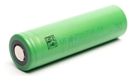
I wanted to power Rezodo with a single 18650 Li-ion cell.
Knowing that the coil eats ~1A when running (100ms per coil !) and that it should run twice per day during max 1s, we can easily compute the power requirements for such a battery... Coil management is obviously negligible in this equation... Most of the power will be eaten by ESP32 when not sleeping.
To get a worst case I did measure the current while ESP32 is running : 40mA when CPUs were awake, and 115mA when Wifi was active. I took a worst case of 150mA
- Assuming that the ESP32 will wake up every 2 minutes (worst case) and stay On during 1 minute. We will get during 12 hours : 150mA * 4V * 1/2 = 0.3 W during 12 hours
- Assuming that the ESP32 will sleep during the whole night : ~0W during 12 hours
daily power consumption : 150mW during 24 hours in average
The Li Ion battery was given for 3400mAh but would realistically store not more than 2000mAh
![]()
So this battery should last 2000/150 = 13.3 days before being empty...
To avoid this "power outage" after 13 days we can add a small solar panel.
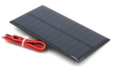
A small 6V 1W solar panel would be enough.
Even in case of bad weather, this panel panel could provide a little output to charge the battery (let say 300 mW).
More than needed to balance the Rezodo comsumption (150mW daily) .
![]()
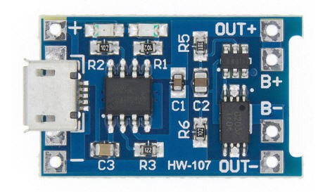
The charger itself will be a cheap TP4056 module:
![]()
It can charge a single Li-ion and has undervoltage, overvoltage and current protection which is perfect for battery safety.
TP4056 has the following features
- Constant Current / Constant voltage charging method. (max curent for charge is set at 1A by default)
- C/10 Charge termination.
- 2.9V trickle charge threshold (for deeply discharged batteries).
- Upper charge stop voltage : 4.2V.
- Soft start inrush current limit.
- Automatic recharge (keeps batteries optimally charged when connected to a charger).
We have now a fully qualified setup with a coil driver, a battery and a solar charger to keep the system running during years. Let's now add a brain to this device!
A brain for Rezodo
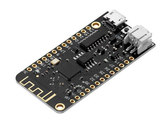
Rezodo's brain will be a ESP32 microcontroller.
![]()
This MCU can go into deepsleep mode.
If you put your ESP32 in deep sleep mode, it will reduce the power consumption (in the range of 10 µA). Having your ESP32 in deep sleep mode means cutting with the activities that consume more power while operating, but leave just enough activity to wake up the processor when something interesting happens.
This feature is perfect for Rezodo as we plan to wake up the MCU every few minutes. A deepsleeping MCU is thus perfect provided we take also care of disconnecting all the actuators/sensors when the system is sleeping. (This is the reason why we choose a step Up DC/DC converter with an enable pin!)
Keeping time
Allowing the network of devices to go into deepsleep mode implies that all the devices should synchronize to wake up at the same time. We have thus to add a Real Time clock and a way to get the time and sync all the clocks.
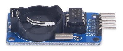
I have thus added a DS1302 Real Time board to Rezodo
![]()
Building the network
The ESP32 has networking capabilities (Buetooth Low Energy, Wifi, ESPnow and ESPNow Long Range)
The best solution for our application is ESPNow Long Range. Expressif claims to reach distances above 500m with ESPNow_LR
I performed tests and got distances above 300m in open sky... So this is a really good solution but it does not allow to achieve 1km range transmission.
The only efficient solution is to use Lora technology
I did benchmark Lora point to point communication and was able to reach 8km range in line of sight.. Realistically 1km is easily achievable even is city environment.
We have thus to add a lora module to our Rezodo.
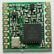
We choose the Semtec RFM95W module which is compliant with European standards (868MHz module)
![]()
For USA you should choose a 915MHz version.
Our Rezodo board will thus have optionnal Lora module and ESPnow Long Range on the same board. It will also offer a connection to Wifi to interface with our home automation system.
Final Schematics
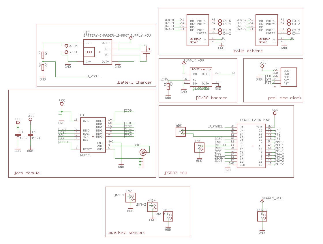
Having all the components we can easily draw the final schematics
![]()
And having the schematics we can produce a PCB!
Rezodo: Long Range irrigation and weather station
Rezodo aims at building a distributed irrigation system and a weather station with farmers. It's also a fully open platform for IoT learning
 JP Gleyzes
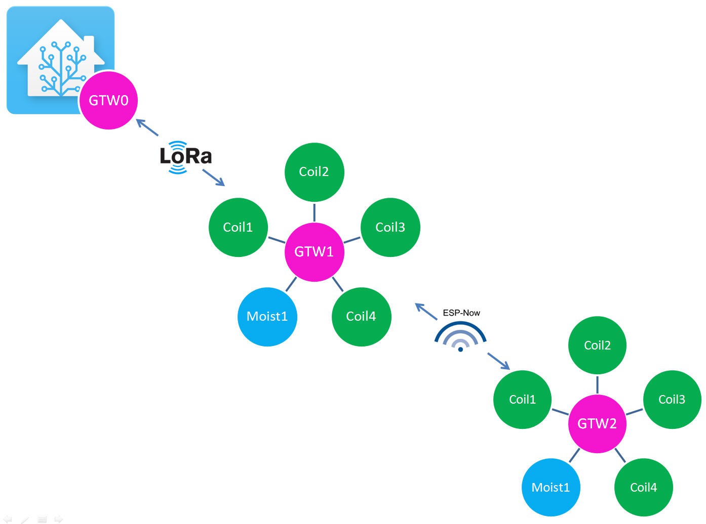 Timm is currently reviewing my modifications and will decide to merge them(or not!) into FDRS master.
