 My Solar Tracker
Hi everyone, we have completed the assembly of the PCB:

WARNING:
To avoid burning out the circuit, set step-down output to 5.0-5.2V before to mount to PCB !
(and secure the screw with a bit of glue)
For this purpose, please use an external power supply as the input, with a voltage value similar to the solar panel being used.
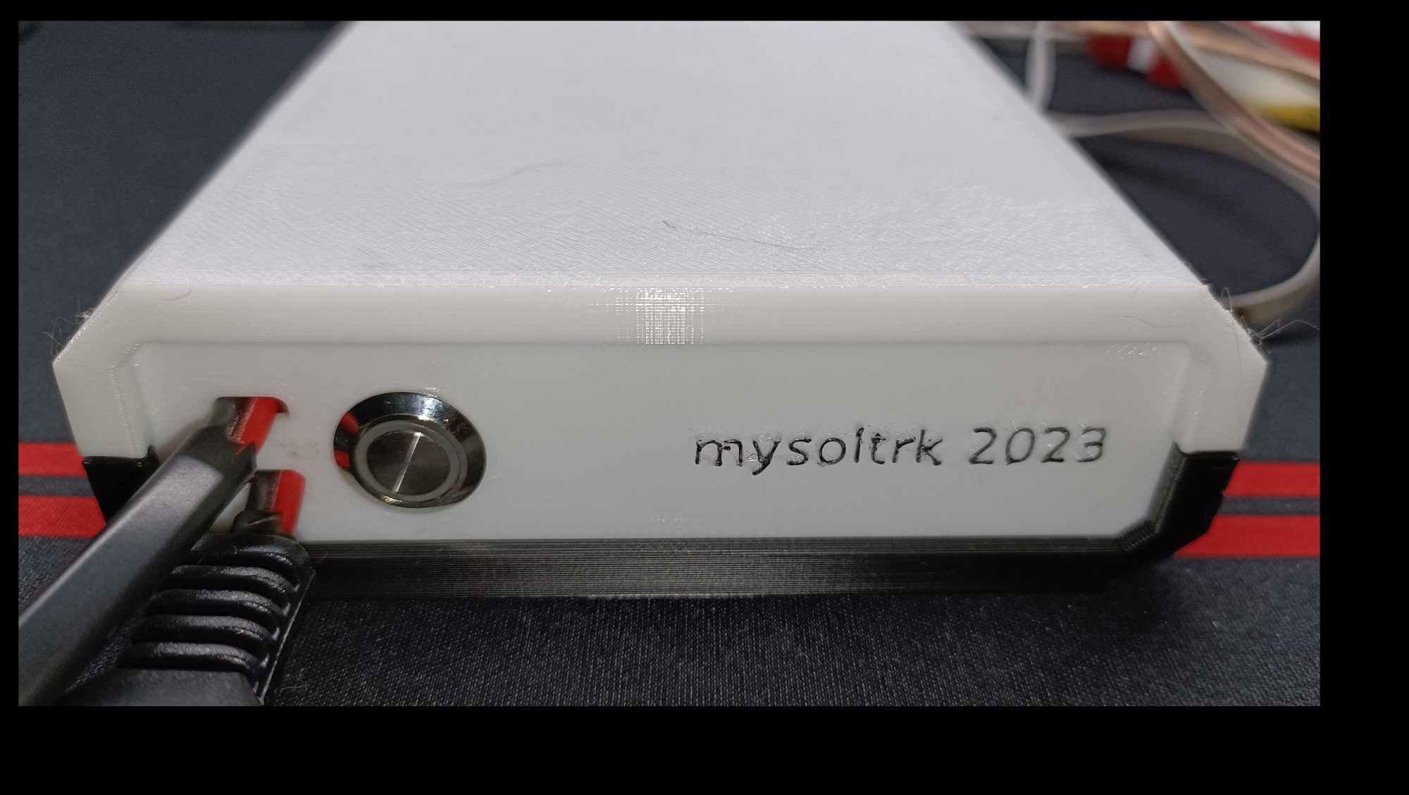
We also prepared a box, the whole thing looks professional to us :)
We are busy to build two working prototypes, with two types of solar panels.
We will update you in the coming days.
Discussions
Become a Hackaday.io Member
Create an account to leave a comment. Already have an account? Log In.