 My Solar Tracker
After having built the actuators, the next challenge is to create a type of support that allows the movements generated by the new three-way support.
Here our approach for the actuators:
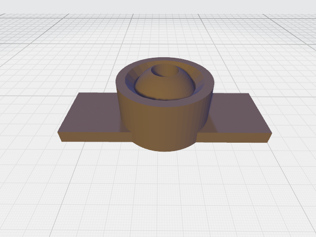
For the panel support:

We have arranged drilled holes to use with screws to lock the support to the panel.
For this project, we've used a solar panel with size 21x19cm, light enough to allow us to experiment with the movements using tape to keep the newly made pieces together:
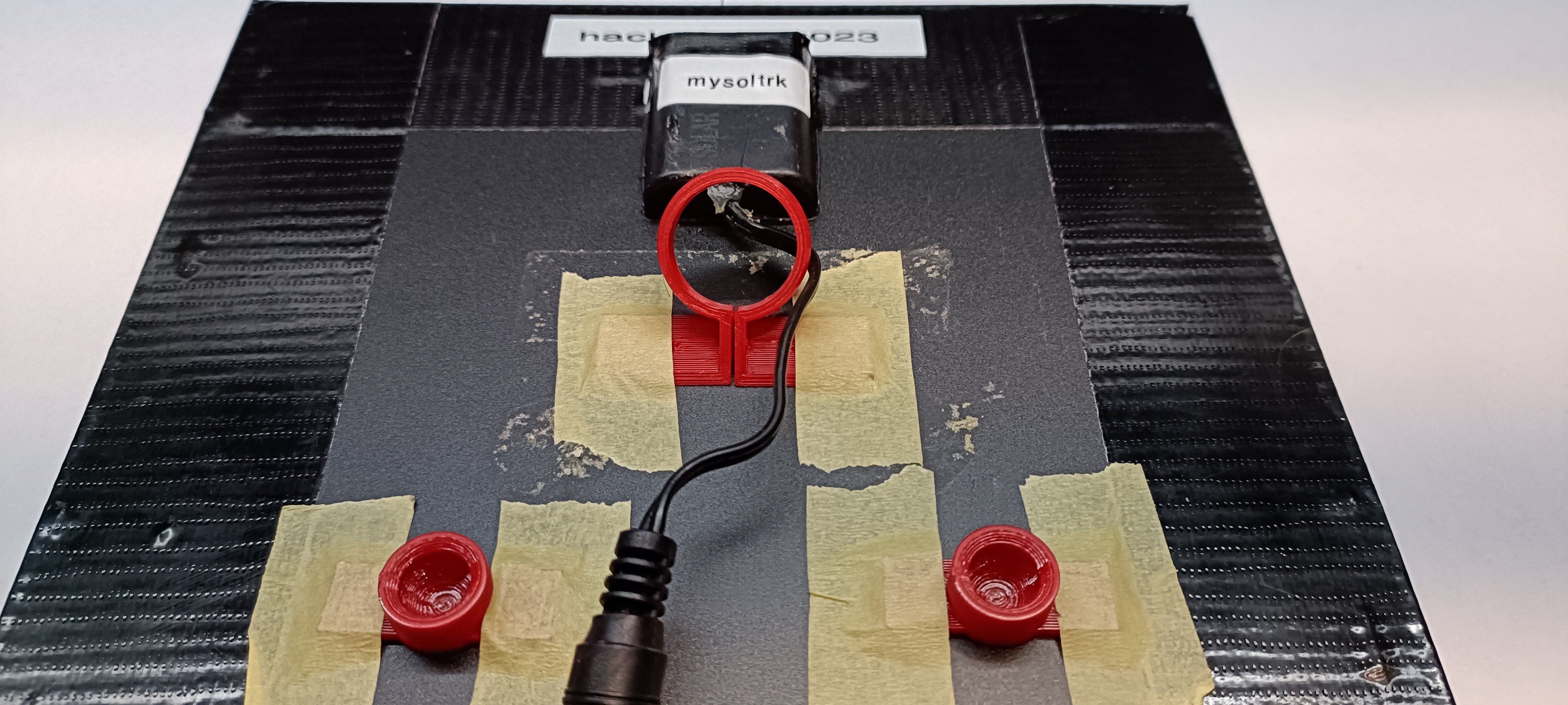
It's not very professional, but it allows us to find the right positioning of the three joints.
The next step is to create a stand for the panel. In this case we found some materials in garage, probably bought in some hardware store time ago for other DYI projects.
For this part of project have fun with your imagination and your dexterity
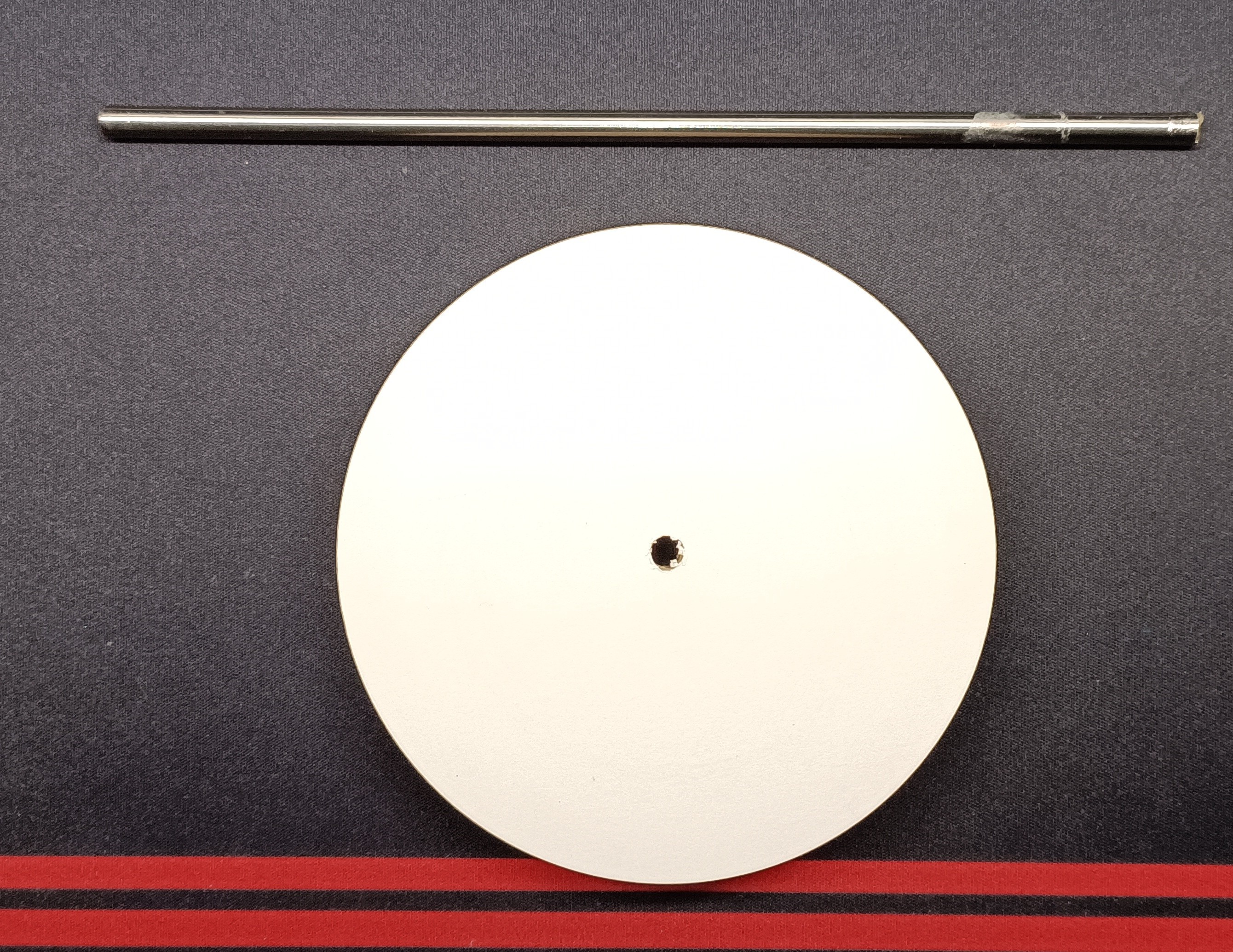
The tube has 6mm diameter and a height of about 20cm, the round stand (used for the base) is plywood of about 12cm in diameter. Obviously, you can use a different stand form.
Here is the detail of how the joint is attached to the panel:
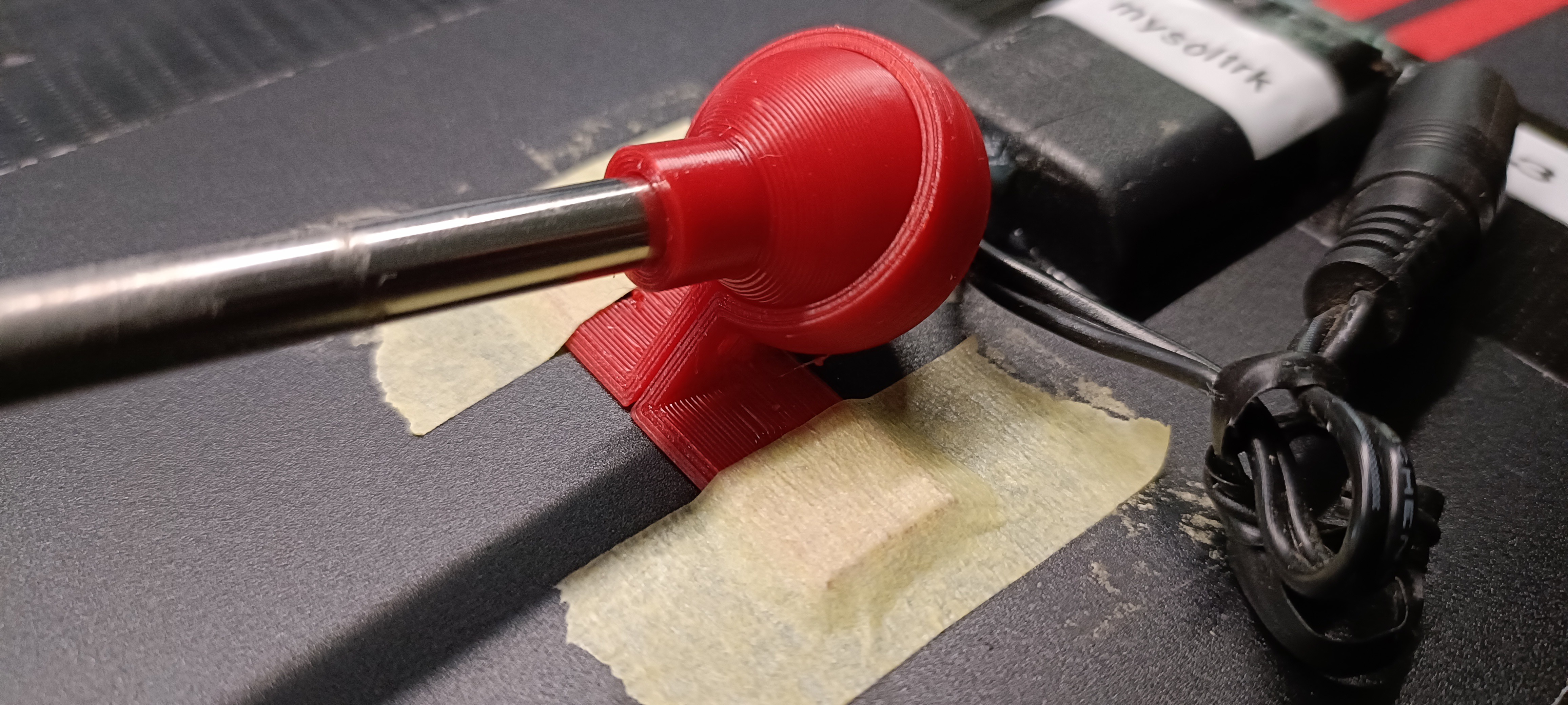
Here final result (for prototype number 1):

Some notes for assembling:
The sphere inside actuator support can be removed easily. Just screw it to the actuator and then you can pull it out.
The rounded plywood square was added during assembling for movements study
Discussions
Become a Hackaday.io Member
Create an account to leave a comment. Already have an account? Log In.