 My Solar Tracker
These days we have focused on transforming the breadboard circuit into a solderable breadboard circuit, adding a small box to enclose everything.
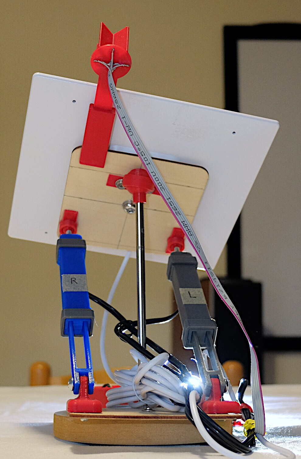
Here is the result of prototype #2:
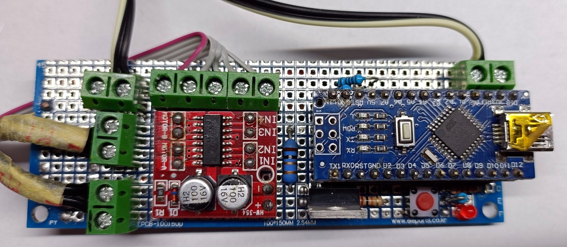
As you can see, all components used on prototype #1 are in prototype #2. We have added a little led for debug (bottom right) connected to the mosfet pin.
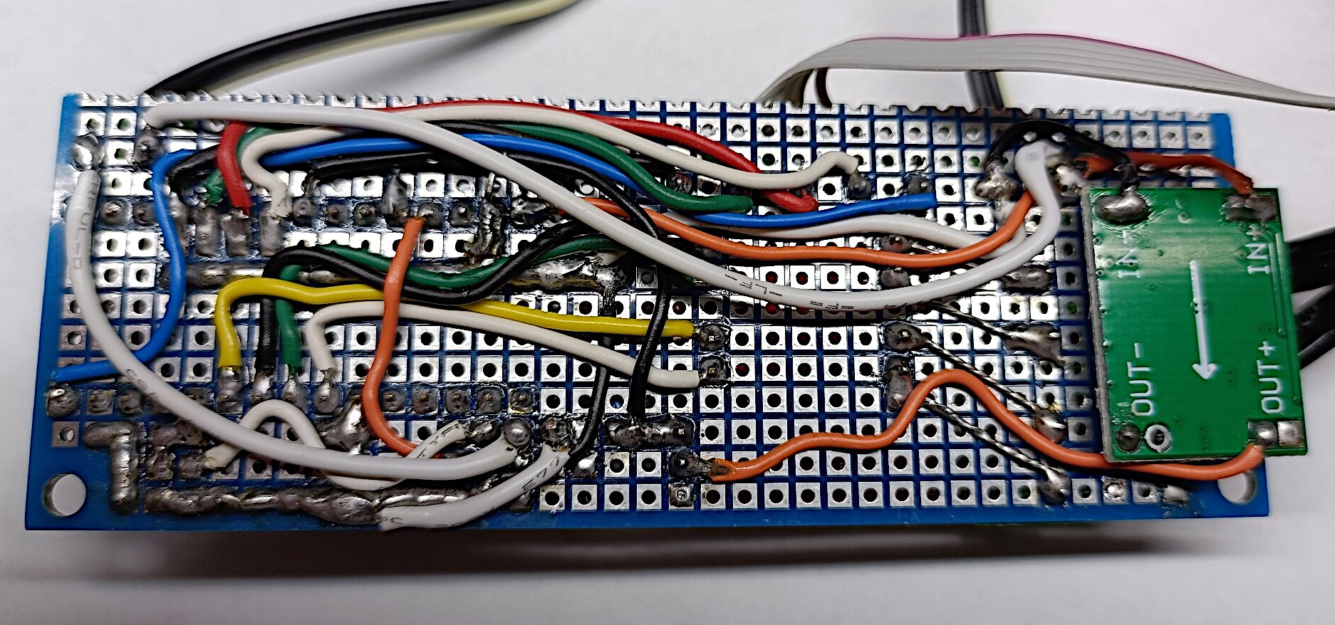
The circuit inside the box:
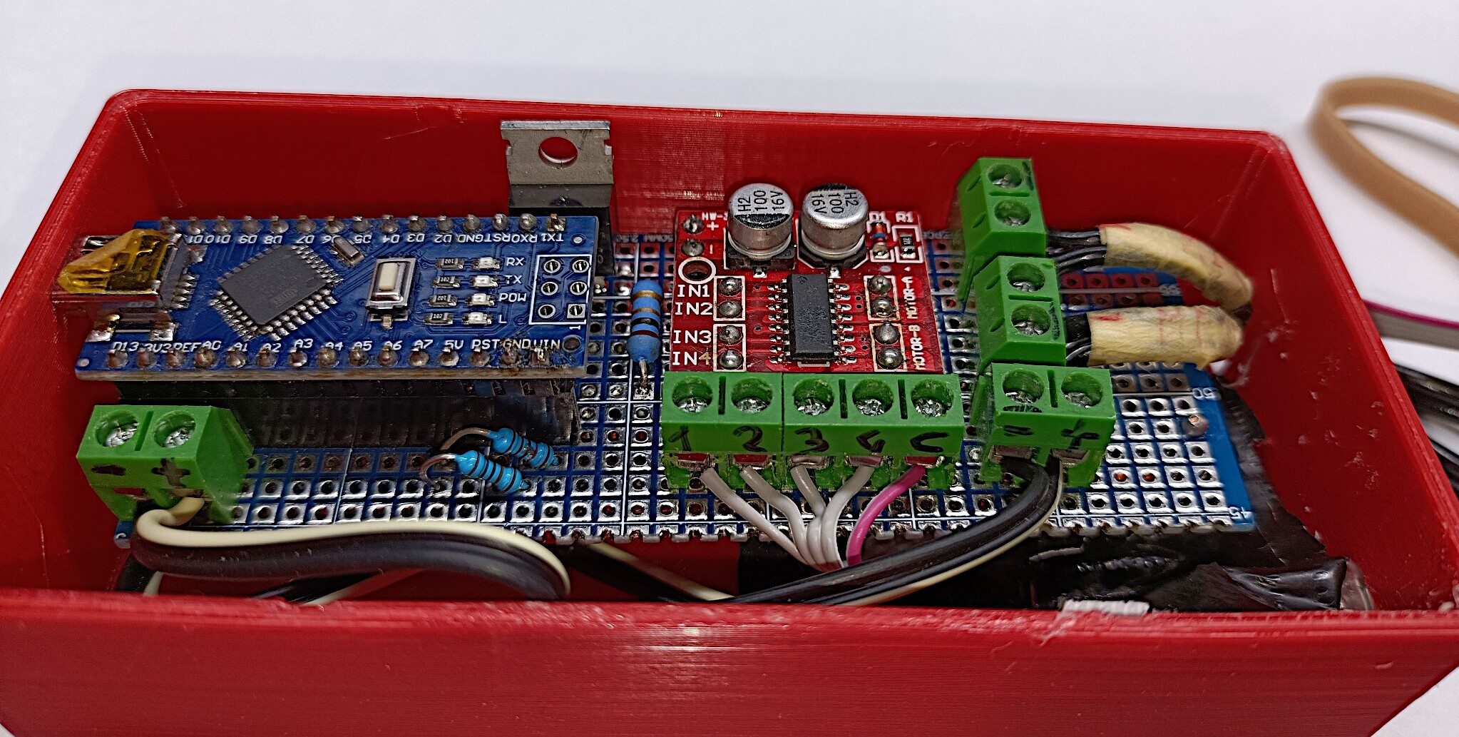
We have added two usb connector for USB IN and USB OUT, fixing with hot glue:


By connecting the circuit to the actuators, to the photoresistors and to the solar panel we obtain this beautiful result to see:
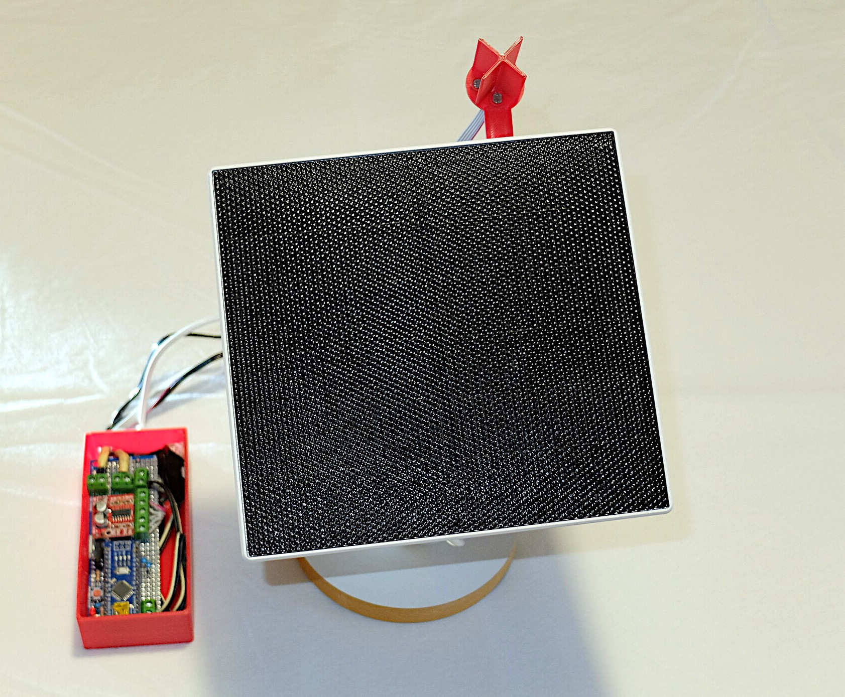
Now we are ready to do some tests outside.
Discussions
Become a Hackaday.io Member
Create an account to leave a comment. Already have an account? Log In.