Close
0%
0%

Positivity Pusher | infinite affirmation generator

Hear a new encouraging phrase with every push

Similar projects worth following
Push this button to have a new affirmation generated and spoken just for you.

You might be practicing mindfulness, learning self-love, or embarking on a challenge. Sometimes repetition is the best medicine.

This self-contained button uses a microcontroller with wifi to connect with a large language model and speech engine for creating unique phrases tailored to your personal needs.


The Positivity Pusher delivers empathetic messages of encouragement at the push of a button. 

Hardware:

The Positivity Pusher uses an inexpensive Raspberry Pi Pico W ($6 new) housed in a repurposed recordable message button (about $3 used). 

Visual feedback is provided by replacing the mic with an LED. By repurposing existing hardware and adding only the most necessary additional hardware, The Positivity Pusher is designed to be easy for anyone to build, with a total cost of under $10.

Software:

The Pico W runs CircuitPython. The script connects over wifi to external APIs for AI text completion and speech generation, playing back the resulting audio file whenever the button is pressed. 

In addition to downloading fresh messages, the code also implements a web-based UI and self-broadcasted access point, where the user can provide their network credentials and customize their message prompt. 

Building Your Own:

Here's what you'll need:

Details can be found here:

More Info:

Positivity Pusher is designed to be made with secondhand parts to maximize enjoyment and minimize cost. It also employs a number of hacky solutions and compromises to achieve it's low cost and simplicity. Here are some highlights:

This page is a work in progress, please check back as additional details will be added!

positivityPusherWiringDiagramV1.0.jpeg

JPEG Image - 76.53 kB - 06/24/2023 at 01:31

Preview

rrspecial.jpeg

JPEG Image - 32.72 kB - 05/22/2023 at 05:33

Preview

  • 1 × Raspberry Pi PIco W $6 new
  • 1 × Message Button approx. $3 used
  • 1 × (not always needed) 2N3904 or similar Transistor $.10 or free if scavenged
  • 1 × (optional) Color Changing LED $.10 or free if scavenged
  • 1 × OpenAI API key approx. $0.50 for a full year of daily affirmations

View all 6 components

  • Getting Keyed

    Steph07/04/2023 at 04:57 0 comments

    Positivity Pusher needs two API keys to function. 

    Here's how to get them.

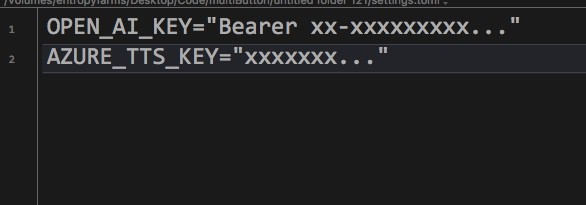
    After each button press, Positivity Pusher connects to OpenAI to generate new text, and Microsoft's Azure cloud services to generate the speech. The keys are basically how Positivity Pusher signs in to those services. Once you have them, you'll put them in the settings.toml file on your CIRCUITPY drive using any text editor. To start, the file should look like this:

    OpenAI:

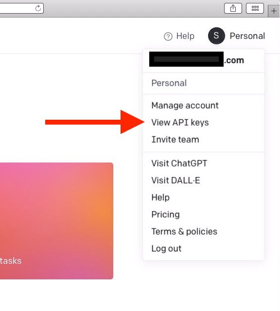
    This one is easy. Just go to openai.com and sign up for an account. You'll have to supply a credit card at some point. Next, click on your profile in the upper right corner of the page and select "View API keys"

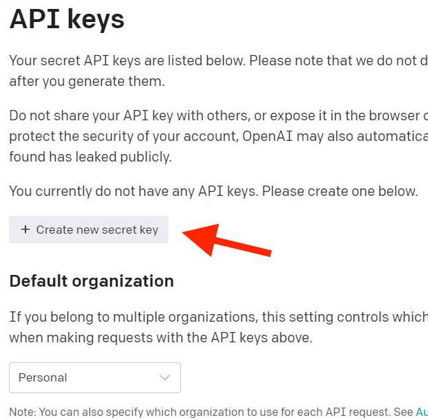
    Next, click the button to generate a new key:

    That's it! You can now copy the API key and paste it into the settings.toml file. Note that this key begins with "Bearer", leave that in place and replace only the x-es. You can only view this key once, so be sure to copy it to somewhere safe. If you lose it, you'll need to generate a new one. 

    Microsoft/Azure TTS:

    This process is a lot harder because it's Microsoft so of course it is. The good news is that it's free. 

    First, you'll need an account. We'll end up selecting a free tier later, but you will still have to provide a credit card in order to get set up. I know it sounds sketchy, but I've done it myself and it's true. The free tier really is free. 

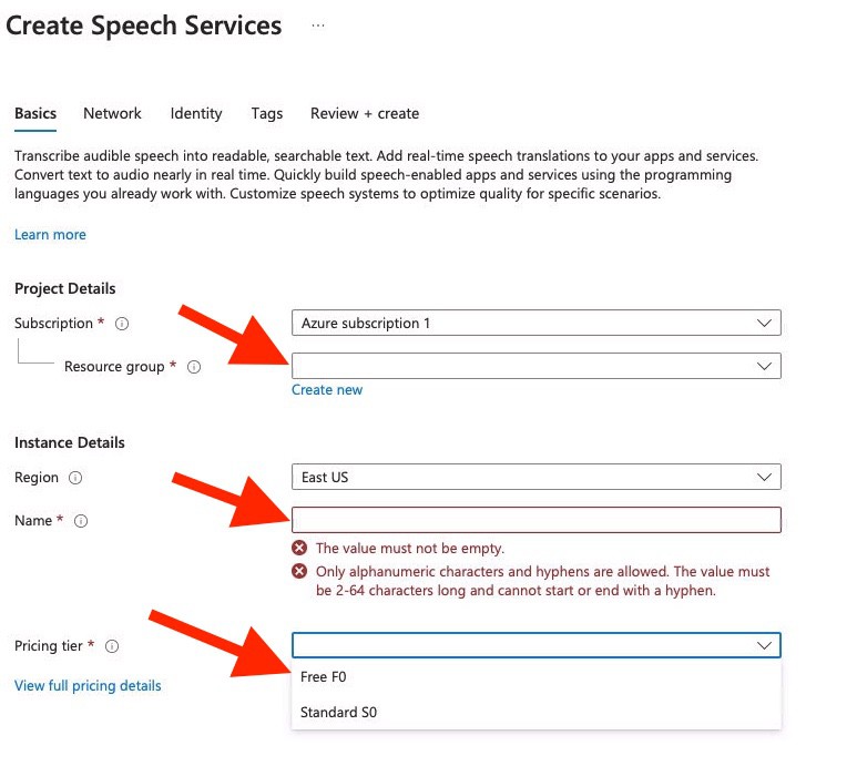
    Once you have your account and are logged in, you'll add a Speech Service to your account. 

    You'll need to choose a name for your resource group and instance. Pick anything, this won't matter much. Also choose the region closest to you.

    Next, choose the free pricing tier, then click the create button. 

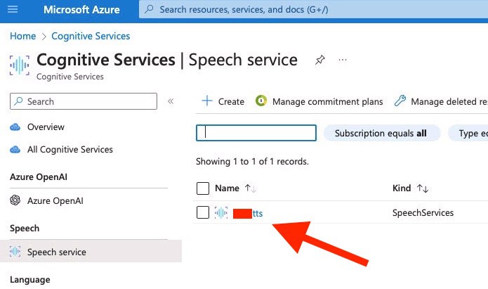
    From the Speech Service page, click on the name of your instance:

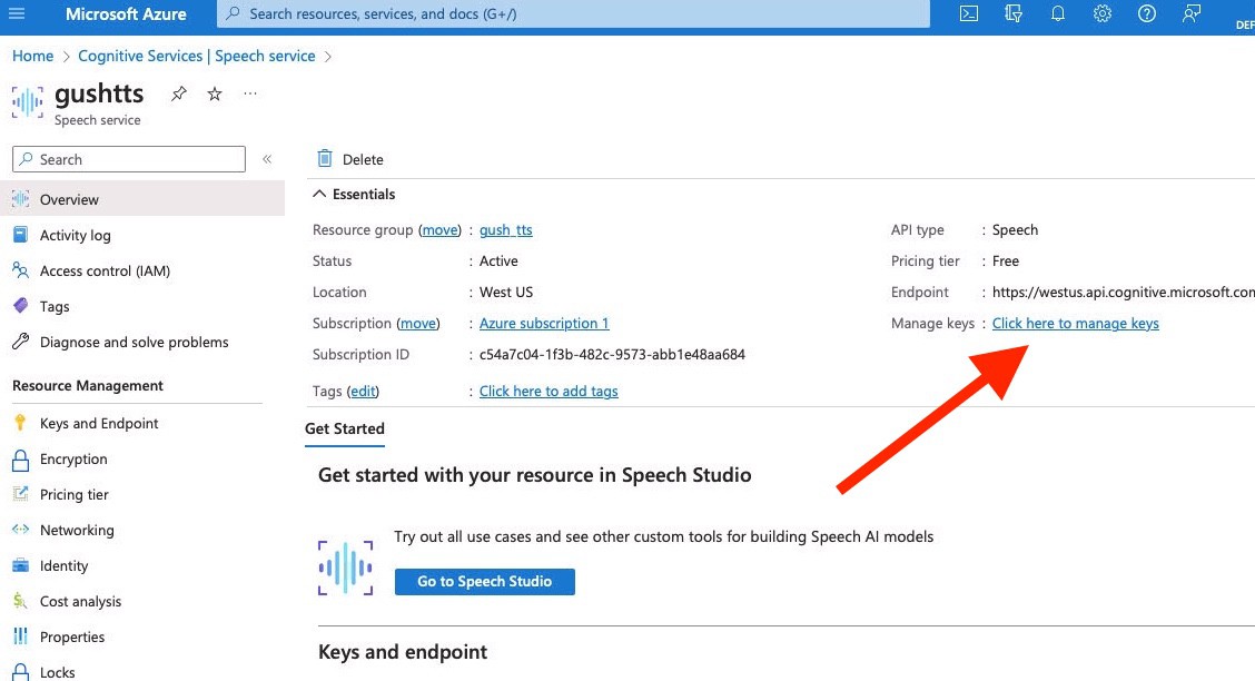
    Now, click to manage keys:

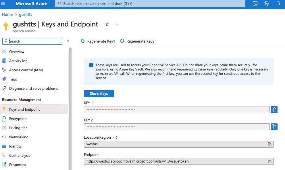
    Finally, you'll be able to copy your key from this page.

    Now that you have both keys, your settings.toml file should look like this:

    • note that these are not my real keys. Don't share your keys on the internet, or post them to your GitHub (sigh)

    API Costs

    Neural Speech Synthesis:

    Microsoft allows a generous 500,000 characters per month on the free tier. By my estimation, that's enough to narrate all of The Hobbit, every month. In my extensive testing of Positivity Pusher, i've never hit the cap, even when pushing the button hundreds of times per day. If you somehow need more affirmations than that, the paid rate is $16 for 1M characters.

    AI Text Generation:

    Positivity Pusher uses the "3.5-turbo" model from OpenAI, which currently (as of July 2023) has a price of $0.0015 / 1K of input tokens and $0.002 / 1K of output tokens. Of course, those numbers alone don't tell us much. OpenAI says:

    Multiple models, each with different capabilities and price points. Prices are per 1,000 tokens. You can think of tokens as pieces of words, where 1,000 tokens is about 750 words. This paragraph is 35 tokens.

    "Input tokens" refers to the tokens that get sent to OpenAI in the form of the prompt, where "output tokens" are the generated response. 

    Positivity Pusher uses about 700-900 input tokens per press, and the response is capped at 100 tokens, usually coming in between 50 and 90 tokens in length. 

    With these numbers, we can calculate that each press of the button costs around $0.0014. At that price, two presses per day x 365 days = $1.00

  • Installing Firmware

    Steph06/24/2023 at 16:40 0 comments

    (Drag and) Drop It Like It's Hot

    Installing the UF2 image

    The Raspberry Pi Pico W comes with a "permanent ROM UF2 bootloader". What do those words mean? Let's dig in. 

    • "Permanent ROM" means this functionality can't be overwritten
    • The "bootloader" is the basic code that loads our real code, sort of like the BIOS of a PC. 
    • UF2 is a file format developed by Microsoft, for use in programming microcontrollers. It stands for USB Flashing Format, and it's used for loading firmware easily over USB. 

    For simplicity, Positivity Pusher is programmed with a custom UF2 image that contains CircuitPython and all the code and other files needed for operation. You'll be done in three easy steps:

    Step 1:

    Download the latest Positivity Pusher Firmware here.

    Step 2:

    Install it! All you have to do is plug in the Pico W to your computer while holding down the BOOTSEL button. A removable drive called RPI-RP2 should appear.

    Now, simply drag the positivityPusher.uf2 file to the RPI-RP2 drive. 

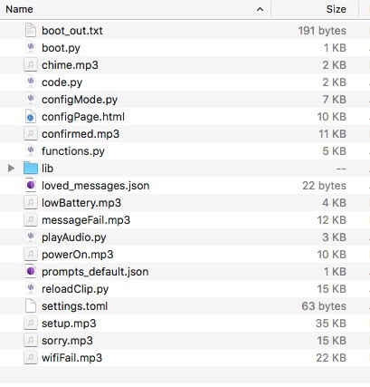
    Once the board reboots, you'll see a USB drive now called CIRCUITPY. The contents should look like this:

    Step 3:

    Almost there! The last step is to provide your API keys for OpenAI and Microsoft's Azure Speech Services. If you need to get those keys, here's how.

    Open the file "settings.toml" with any text editor. You'll see this:

    OPEN_AI_KEY="Bearer xx-xxxxxxxxx..."
    AZURE_TTS_KEY="xxxxxxx..."

    Overwrite the placeholders with your actual keys and save the file. (note: the OpenAI key must start with "Bearer ", don't replace that part)

    That's it! Your firmware is now installed and ready. 

    You'll probably hear an audible message asking you to set up wifi now. Press the "configure" button to reset your board and enter the wifi setup process. Supply your network credentials and prompt information. You're now ready to get affirmations!

  • Score A Free Transistor

    Steph05/26/2023 at 04:26 0 comments

    If your button is made by Learning Resources or is a similar clone, it likely has a transistor right on its PCB that works great for amplifying audio in the Positivity Pusher. The only problem is that it's a tiny surface mount version, which can be a pain to work with. 

    Well, actually...

    The button has two amplifiers, one for the speaker and one preamplifier for the microphone. I'd love to tell you how to use the amplifier that was designed for driving the speaker, but I can't. Because...

    I don't know how.

    Depending on what version of the PCB your button came with, its speaker is either connected to a black blob or a mysterious IC for which no data sheet is available. Either way, I can't make it work for me. If you have information about making the built-in amplifier work, I'd love to hear about it. What I can tell you about is...

    Misusing Repurposing the Preamp

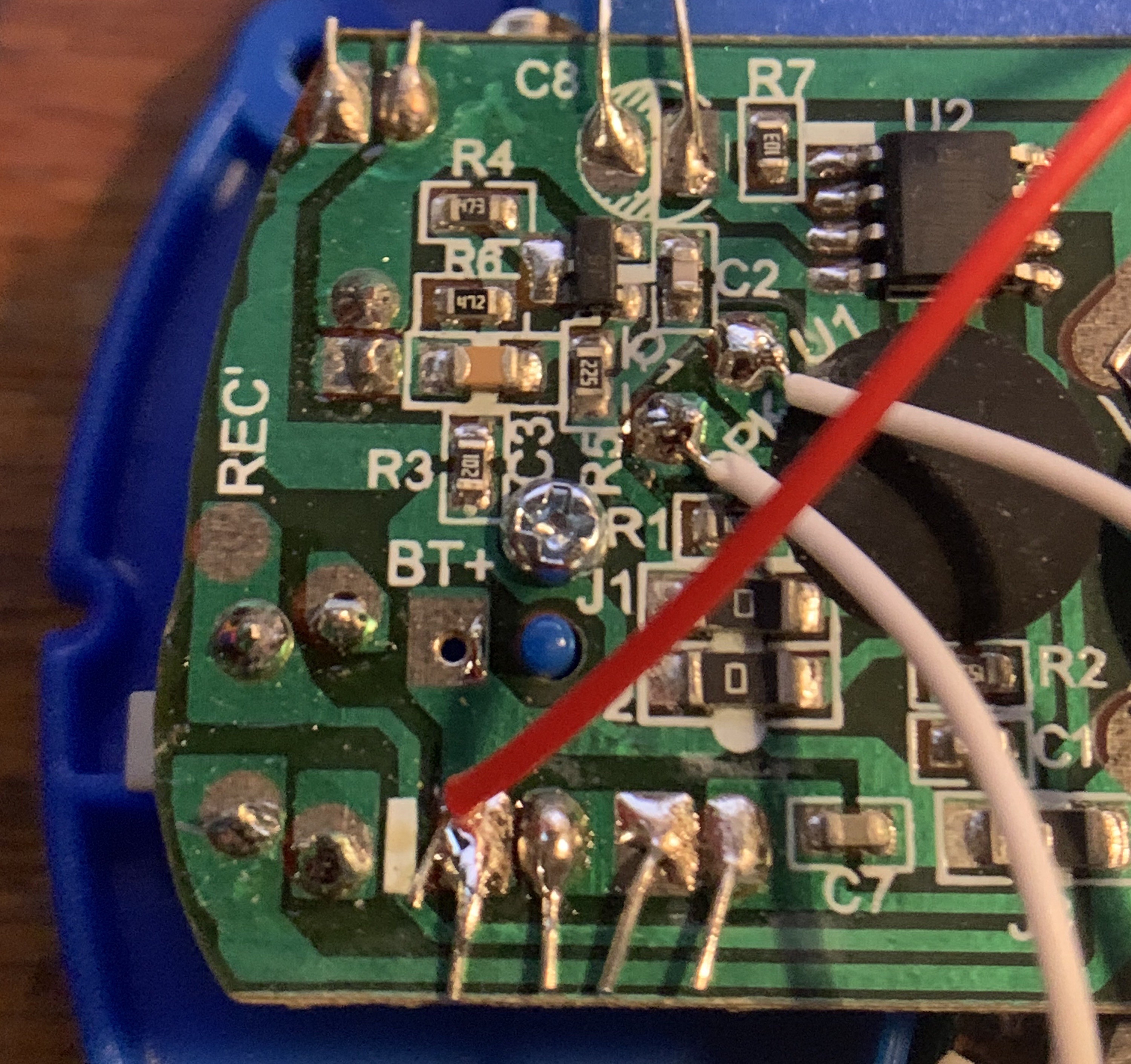
    Take a look at the upper left corner of the PCB, near the microphone. This bunch of components brings the mic signal up to a voltage range compatible with the recorder.

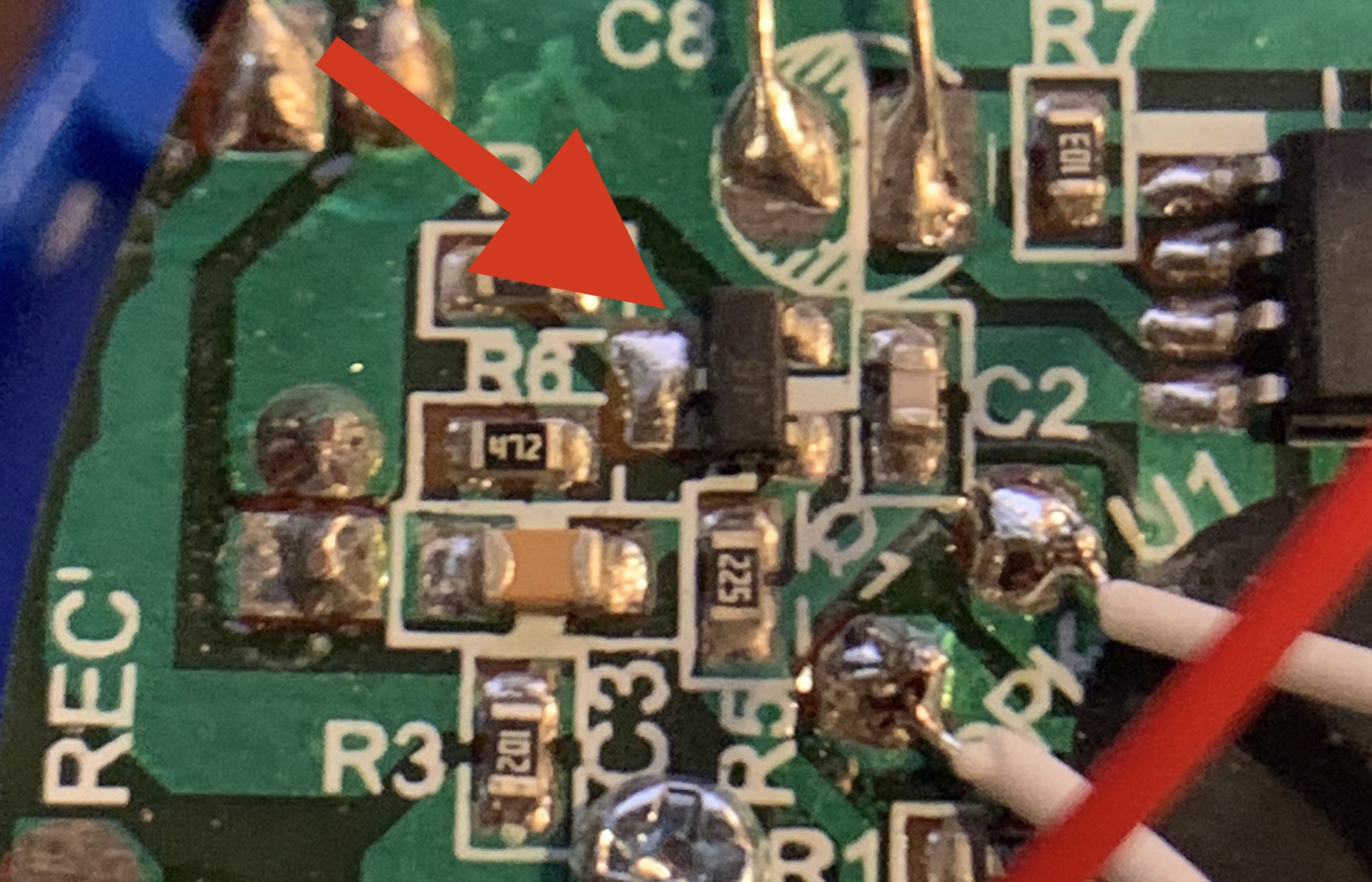
    Let's zoom and enhance:

    A visit to smdmark.com  reveals the the faint "J6" labeled component to be a S9014 Silicon Epitaxial Planar Transistor, Pre-Amplifier, low level & low noise.

    Perfect! Ok not perfect.

    We're sorta after a high level & high noise type of situation here. But the price and availability of this one can't be beat! I wonder if it can be bent to our will.

    It can!

    But before we can use it, we have to remove it.

    And removing SMD stuff isn't that easy.

    Here's what I recommend:

    1. Tin the tip of a short bit of wire. Put it aside for later.
    2. Use desoldering wick on the side with the single lead. Remove as much solder as you can. 
    3. Grab the transistor with tweezers. 
    4. Heat both leads on the other side with one big blob of solder.
    5. Lift the transistor off the PCB.
    6. Immediately solder the piece of wire from step 1 to the single-side lead. It's much easier to work with and position the transistor this way. It's otherwise very easy to lose and impossible to find if you drop, and there's only one on the board. 

    As per the datasheet, pins 1 and 2 are the base and the emitter. Pin 3, which has your handle soldered on, is the collector. 

    To add the transistor to the Pico W:

    1. Melt some solder onto the GPIO1 pin and the adjacent GND pin.
    2. Turn the transistor so the J6 label is facing away from the Pico W.
    3. Solder the transistor base to GPIO1 and the emitter to GND. 
    4. You can now desolder and remove your handle! 

    Once your Pico W is in place, you'll wire one lead of the speaker to the transistor's collector pin, where the handle used to be.

    That's it! You can read more info about the "theory" behind this amplifier circuit here.

    Results

    Our misapplied preamp turns out to make a very plausible small amplifier! Combined with the 8ohm speaker in the button, our amp can generate uncomfortably loud volumes with manageable distortion and a workable frequency response.

    Notes

    Some PCBs come with a transistor labeled DAG3 instead of J6. The DAG3 turns out to be a 2SC5343SF transistor, which has the same pinout as the J6. 

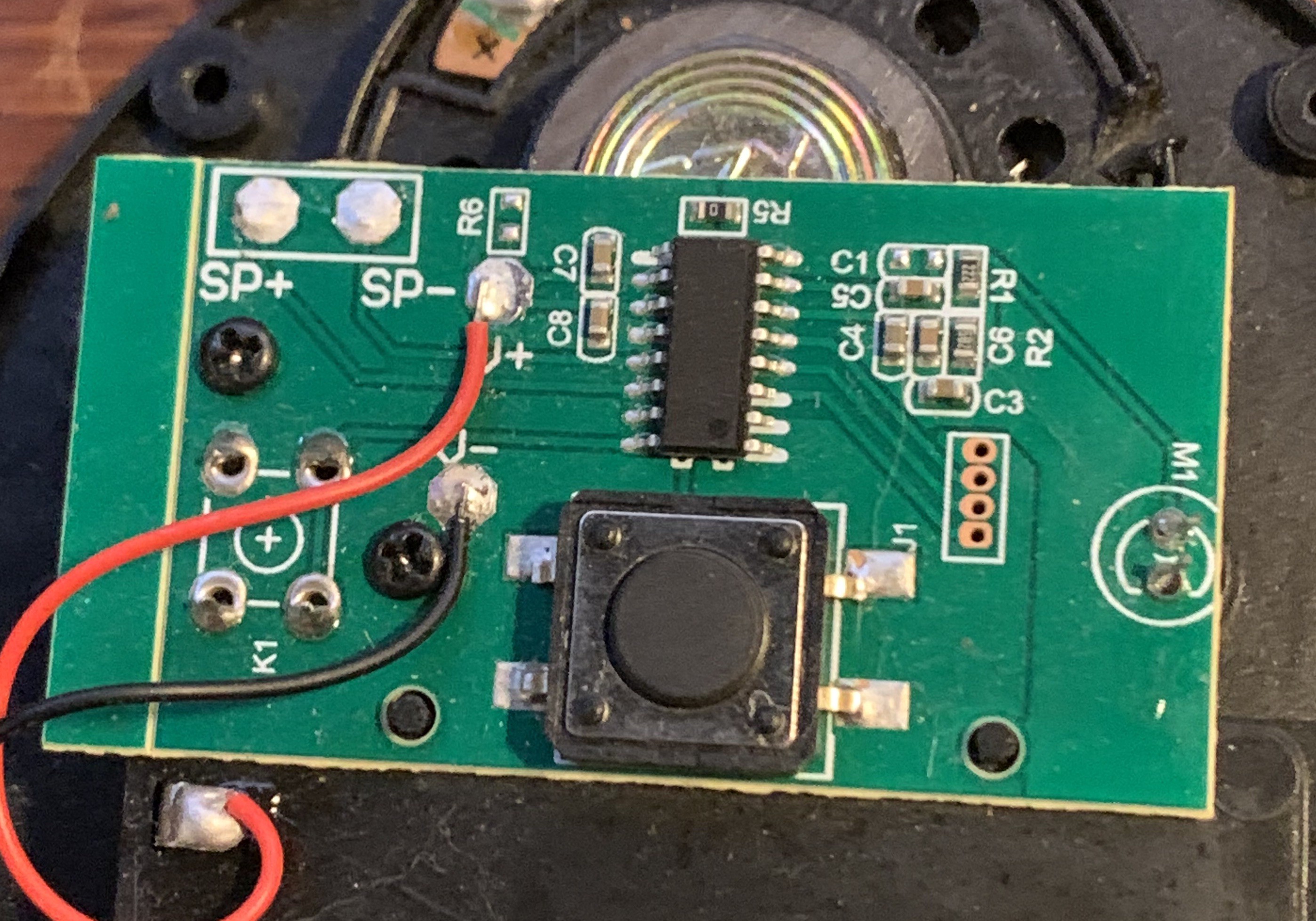
    Some types of buttons, sadly, come with no transistor at all:

    If you've ended up with a button like this, you'll need to get your transistor somewhere else.

  • Disassembly

    Steph05/25/2023 at 22:57 0 comments

    Started From The Bottom

    The bottom of your button will have four little rubber feet. These feet conceal four screws. 

    Start by carefully prying up the rubber feet. These are easy to misplace, as they are simultaneously round, bouncy and sticky. Which means they have three means of escape. Stick them right back to the bottom of the button somewhere. That way, they'll still act as feet, and you won't lose them. As easily.

    If your button has a little red side button, this round red cap is not attached to anything. Once the button is open it will fall out and it will disappear forever. Prevent this fate by sticking some tape over this side button before you open anything.

    Now, take out the screws. You're gonna lose some of these, It's just a given. 

    Separate the bottom from the rest of the button. You did it! 

    The upside-down button top makes for a swell place to keep any screws you've managed to not already lose. 

    But Wait There's More

    Reassembly

    Putting it back together is simple but I do have some pointers.

    For buttons with the red side switch, I move the tape holding the cap from the outside to the inside. It doesn't affect the button's operation and keeps the cap in place.

    The actual top button dome slots into the sidewall with two easy-to-miss notches, so you'll want to rotate it until is falls into place.

    Finally, I've found that the button really only needs two screws to hold everything together. 

  • Embiggen the Smallest Mp3

    Steph05/04/2023 at 03:39 0 comments

    The Positivity Pusher utilizes Microsoft's neurally generated text-to-speech API. Any other service offering TTS could be substituted, but the Microsoft offering has some compelling features:

    1. Cost - It's free up to 500,000 characters of generated text per month. That's about a novel worth of audio
    2. Emotion - The API generates speech with convincing, selectable styles like 'friendly,' 'sad', and even 'empathetic'
    3. Flexible - A wide selection of voices, languages, and output formats are available

    While the service is able to stream out broadcast quality audio (48khz 16bit uncompressed), we are more interested in the low-res side of the offerings. We need the smallest files we can get, for a few reasons:

    1. We are working in an extremely memory constrained environment. While our program is running, we have access to about 140k of RAM. The onboard flash memory has less than one megabyte available to store everything. 
    2. Smaller files download faster, and faster download times extend battery life.
    3. Audio quality is inherently limited by the inexpensive little speaker in the button, and also by our use of 10-bit PWM to generate the audio (the Pico has no dac), so our file doesn't need a lot of resolution.

    The smallest file we can request from the API (and playback in CircuitPython) is a 16khz sample rate, 32k bitrate mp3 file. For the duration of speech that the Positivity Pusher generates, those files end up being 40-80kb in size. That's pretty great, especially considering that the same audio as a wav would take up around 500kb, which wouldn't even fit in our storage. So 50kb is small, but we can get it even smaller.

    Here's the Trick

    Part 1

    The text-to-speech API allows us to specify the rate and pitch of the speech. We can request a 100% increase in rate, making the model talk twice as fast as it usually would, and also a 100% increase in pitch. The result is effectively the same as a clip that's played at 2x speed. 

    Part 2

    CircuitPython allows us to specify the sample rate used in playback. If we play our 16khz file back at half the sample rate (8khz), our 2x speed clip will be slowed down by 50%, back to the normal speed. Additionally, the pitch will be lowered by the same amount, bringing our voice back to normal pitch as well. 

    • note: In actual practice, we use 10khz for the playback rate because a +100% pitch request doesn't raise the result by a full 100%

    All the Fun, Half the Heft

    By employing this tactic, we shrink the size of the MP3 by half. The clips download faster, which saves battery, and we save a ton of storage space. The resulting drop in audio quality barely perceptible (if at all) considering the limitations of the amp and speaker.

  • Turn Down for What

    Steph05/04/2023 at 02:44 0 comments

    As of this writing (May 2023) CircuitPython has no way of boosting the volume of an audio file during playback. The 'level' parameter goes from 0 to 1, meaning you can turn stuff down, but not up. 

    In situations where audio is being downloaded from outside sources, as in The Positivity Pusher, it would be useful to have the ability to apply additional gain in software. We just don't have that ability. 

    A Bad but Functional Workaround

    In CircuitPython, you can play single clips, and also 'mixer objects', which can simultaneously play multiple clips. My original idea was to make a mixer and play the clip twice at the same time. 

    For unknown reasons, this doesn't work. The clip(s) play but with missing chunks. 

    What does work is creating two identical clips and playing then both in the mixer. The execution looks something like:

    from audiopwmio import PWMAudioOut
    import audiomixer
    from audiomp3 import MP3Decoder
    
    audio = PWMAudioOut(board.GP21)
    mixer = audiomixer.Mixer(buffer_size=1024, voice_count=2, 
                           sample_rate=10000, channel_count=1,
                       bits_per_sample=16, samples_signed=True)
    
    theClip = MP3Decoder('clip.mp3')    
    theClip2 = MP3Decoder('clip.mp3')
    
    audio.play(mixer)
    mixer.voice[0].level = 1    
    mixer.voice[1].level = 1    
    mixer.voice[0].play(theClip)    
    mixer.voice[1].play(theClip2)
    

    Drawbacks

    This method uses twice the memory because it loads the same MP3 into RAM two separate times. Additionally, the resulting volume boost is a modest but noticeable 6dB. Perceptively speaking, it does not "double" the volume in the sense of making the speaker twice as loud as it was before. In the case of the Positivity Pusher, this method raises the volume from a level that requires leaning in to hear, to a level that can be comfortably heard while the button is sitting on a desk and the user is sitting or standing nearby. 

  • Getting Amped

    Steph05/04/2023 at 01:30 0 comments

    The Positivity Pusher uses PWM to generate it's audio output. The GPIO pin produces enough volume to drive small headphones, but to do any serious speaker shaking we'll need to amplify that signal. 

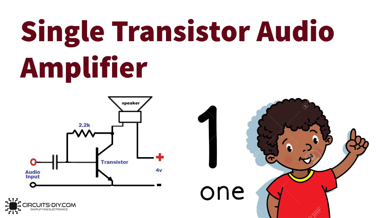
    In keeping with the project's ethos, I wanted to use a circuit with the most simple possible execution, as well as using salvageable parts. Looking around for simple audio amplifiers, I found many "simple" circuits with dozens of (sometimes exotic) components and complicated theories explaining their operation. Eventually, I zeroed in on this design with one transistor and just two other components. You know the circuit is simple when it comes with clipart of a child:

    I took this design and further reduced the complexity by a factor of 66%, by just ditching the capacitor and resistor entirely. Streamlining!

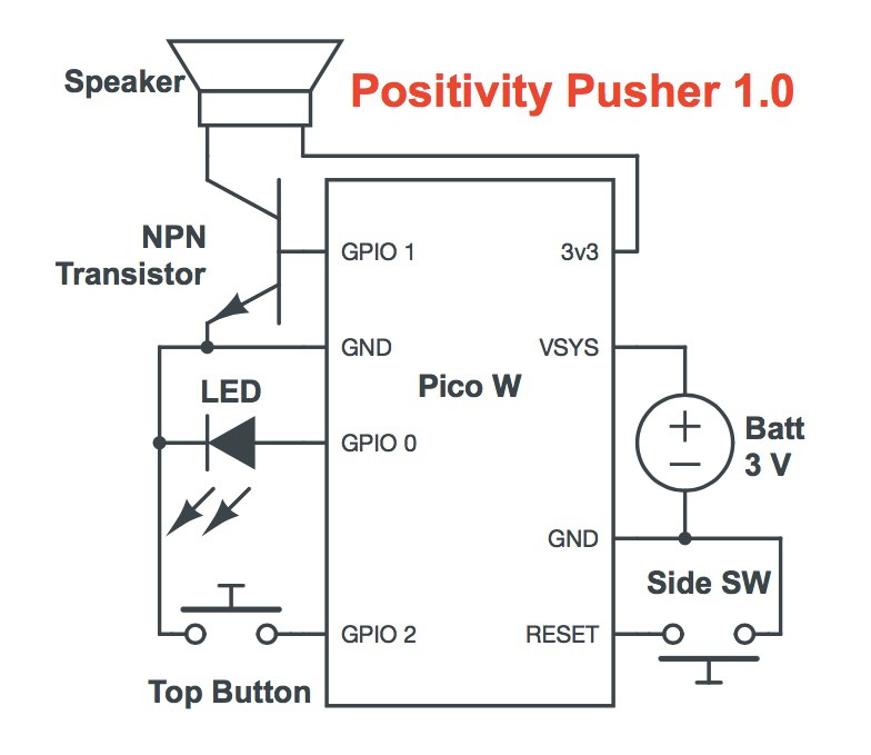
    In the Positivity Pusher version, as seen in the wiring diagram here, +3.3v is fed directly into the speaker from the Pico's 3v3 pin. It then flows into the collector of the transistor and out of the emitter, to ground. The weak audio signal is modulated onto the transistor base pin, resulting in the amplification of the signal through the speaker. 

    When I tried to seek advice about my amplifier design, people online told me that it was "not good." Unfazed, I kept inquiring. They told me I should "use a breakout board" or "the famous LM386." I told them I want to keep it simple. That's when they told me that I should "read some textbooks" and I "shouldn't trust random schematics on the internet" and also that my circuit is known as a "Russian Roulette Special."

    Well... 

    Can't Argue with Success

    I think my single part amp is pretty neat, and I don't think it's dangerous!* And despite what smart people online would lead you to believe: it works! But it isn't perfect. In fact...

    It's Pretty Far From Perfect. 

    • It drives DC through the speaker. 
    • It's not efficient. At all. 
    • The frequency response is not flat. At all. 
    • Probably other bad stuff I'd know about if I read a textbook.

    However, it Has Two Major Benefits!

    1. Minimalism: You can't reduce the part count any further than this.
    2. It really works! Opinions aside, the design verifiably boosts an audio signal. 

    But how bad is it?

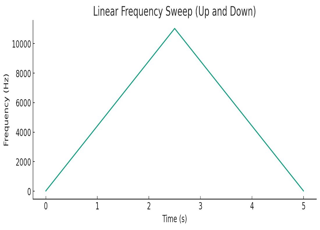
    To get a sense of how the amp is performing, I made a test file for playing back through the amp and speaker. This is a 22050hz wav file, so the top frequency it can reproduce is 11khz. Here's a graph of the frequency over time:

    And here's a spectrograph of our amp playing that frequency sweep through the speaker in a button.

    You can see that our amp introduces some serious harmonics. The line you see following on either side of the main frequency is the second order harmonic. The noise in the middle of the pyramid shape is caused by weird harmonics produced when our signal approaches the Nyquist frequency. The PWM technique used to generate the audio may be responsible for some of this noise as well. 

    Good News

    The spectrograph is color coded. The purple areas are the loudest part of the signal, with red the quietest. Happily, the purple region in our spectrograph is between about 400hz and 4000hz, which corresponds almost perfectly with the range of human voice. This means our speaker will produce louder sound in the voice range, perfect for a project all about speech.

    In practice, this single transistor amp produces easily intelligible human speech with good volume and relatively low noise. 

    Having said all that, you could definitely do better. Basically any other amp design will be an improvement on this one. But! Before you try to improve on this design, I find that it produces plenty of volume and fidelity. I encourage you to try this simple version- it might be good enough for you! 

    *if you think this amp is dangerous please do drop me a note!

  • Ethos and Backstory

    Steph05/03/2023 at 07:41 0 comments

    Simple Access to Complicated Systems

    While designing the speech and thought synthesis system for a robot radio show host, I discovered rather accidentally that the GPT3 AI text generation model, when properly prompted, was capable of providing wholesome personalized affirmations. 

    Friends who met the robot and received an affirmation from it were genuinely touched by its tender words. They expressed a desire for something that they could incorporate into their daily lives and interact with directly to produce these encouragements and kind works. The Positivity Pusher is the result. The first four were built as holiday gifts and presented to recipients in late 2022.

    Here are some important factors that shaped the design.


    Avoid New Parts When Possible

    Since the Positivity Pusher is meant to inspire warm and positive thinking, it's design attempts to avoid materials which might invoke negative feelings due to social or environmental impact.  Consider the benefits of used and second hand materials:

    • Low carbon cost - buying used stuff locally means there is little or no additional carbon footprint in manufacture and shipping of materials. 
    • Diverted waste stream - reusing already existing and unwanted buttons keeps them out of landfills and prevents additional manufacturing.

    The button:

    The Positivity Pusher is based on recordable buttons often used in pet training. The owner will record a short message on the button like "Walk" or "Treats," in the hopes that the animal will learn each button's meaning, and use them to communicate with the owner. 

    In cases where the animal turns out to be of the more traditional non-verbal variety, these buttons often end up in flea markets and thrift stores or returned to  big online retailers. 

    A quick search online as I'm writing this revealed two sets posted for sale online near me within the last 24 hours alone:

    There seems to be an abundant supply of these buttons in the used market. 

    Choose a used unit and feel no guilt about unsustainable manufacturing!

    The brains:

    The original four Positivity Pushers were each fitted with second-hand Raspberry Pi Pico W microcontrollers. These have since proven to be harder to acquire used than the buttons, but it is possible! I scour places for local reselling like OfferUp and Craigslist. The Pico W costs just $6 new, so buying a used model often costs just as much (or more) as a used one.

    The Positivity Pusher uses very few of the available GPIO on the Pico W, and which pins you choose to use is very flexible. As such, a Positivity Pusher can be a great way to reuse units that have some broken or burnt-out pins and can't be used for their original purpose.

    If you're up for some code modification, other microcontrollers with WIFI, like the ESP32 line, might be more readily available used, and should work just fine. 

    The batteries:

    The Positivity Pusher can run on any type of AAA battery: alkaline, rechargeable or lithium. The best lifespan comes from lithium, but these are not reusable. If using non-rechargeables, the batteries will still have some charge left  over even when they can't run the button anymore, so they can can be re-deployed for second duty in low-consumption devices like remote controls. 

    The Basics:

    The rest of the components in the Positivity Pusher are simple and inexpensive: one transistor and one LED. Both can be easily salvaged from other broken electronics at no cost. 

  • Pusher Power

    Steph05/02/2023 at 03:31 0 comments

    How Low Can You Go

    For powering the Pico W, page 15 of the datasheet specifies a lithium cell or 3x AA batteries when away from USB power. It also says you should use a diode to prevent USB voltage from back-powering the batteries. 

    We won't be doing either of those things. 

    Doing more with less

    1. We have no space in our button for three AA batteries. The Positivity Pusher is based on commonly available recordable buttons which have a battery compartment for two AAA batteries. Will that be enough to power the Pico? The answer is yes! 
    2. That protection diode causes a voltage drop. Not ideal for maximizing lifespan, so it's omitted it in the final iteration. This does introduce the possibility of a....

    SAFETY ISSUE!

    If you plug the Pico into USB while also powering it from the batteries, the batteries will get really hot. If you don't notice right away, something worse might happen. If you're going back and forth between batteries and USB power, I strongly recommend leaving the diode in place until the coding is finished and the button is closed. Additionally, it might be a good idea to cover the Pico's USB port with a label reminding future-you to remove any batteries before plugging in. 


    Power Hours

    The Pico W needs a minimum of 1.8v. 

    The Positivity Pusher's button compartment wires the batteries in series, which will deliver 3v using non-rechargeable batteries and about 2.4v with rechargeable batteries. 

    A safety diode will introduce a voltage drop. Exactly how much depends on the type of diode, but many common types will drop .7 volts. That's enough to drop the voltage of rechargeable batteries to 1.7v, not enough for the Pico to operate. 

    Runtime Expectations

    A button should last at least a month on one set of batteries.

    The capacity of two AAA batteries will be somewhere in the 2000mah range depending on type. Power consumption looks something like this:

    Mode:Deep SleepAudio PlaybackNetworking
    Power:1.4mA50mA100mA

    After playing a clip and reloading the next one, the rp2040 processor will drop into deep-sleep mode, where it spends the majority of it's time. In this mode, power consumption should be a scant 1.4mA. 

    While playing audio or downloading clips, power consumption can be as high as 100mA (including the indicator LED).

    Total runtime is influenced by battery type, frequency of presses, and even distance from the wifi router. Using a battery life calculator, I estimate that with non-rechargeable lithium batteries the button should last more than two months, even with 5 button pushes per day. 

    This page will be updated with real-world runtimes once they have been measured. 

  • Wiring

    Steph04/18/2023 at 07:38 0 comments

    Hatchet Job 

    How the positivity sausage is made. 

    At its heart, the Positivity Pusher is a pretty dirty hardware hack. It tries to do a lot of good without a lot of parts. As you'll see in the following section, corners are cut, rules are bent, and on the rare occasion that a datasheet gets consulted, it's ignored. 

    The upside to this hackery is simplicity. 

    • The cost is low.
    • The needed skills are very low. 
    • The part count for this project is super low.

    The barriers to entry are therefore extremely low.

    If you can solder, you can build a Pusher.

    ...and if you can't solder, this is a great project to learn with.

    Remember that the button comes with almost all the pieces you need: the battery holder, both switches and the speaker. Many buttons will even have a surface mount transistor you can salvage if you're an advanced soldering iron user.

    Once you've opened the button it's time to get started!

    Without a Trace

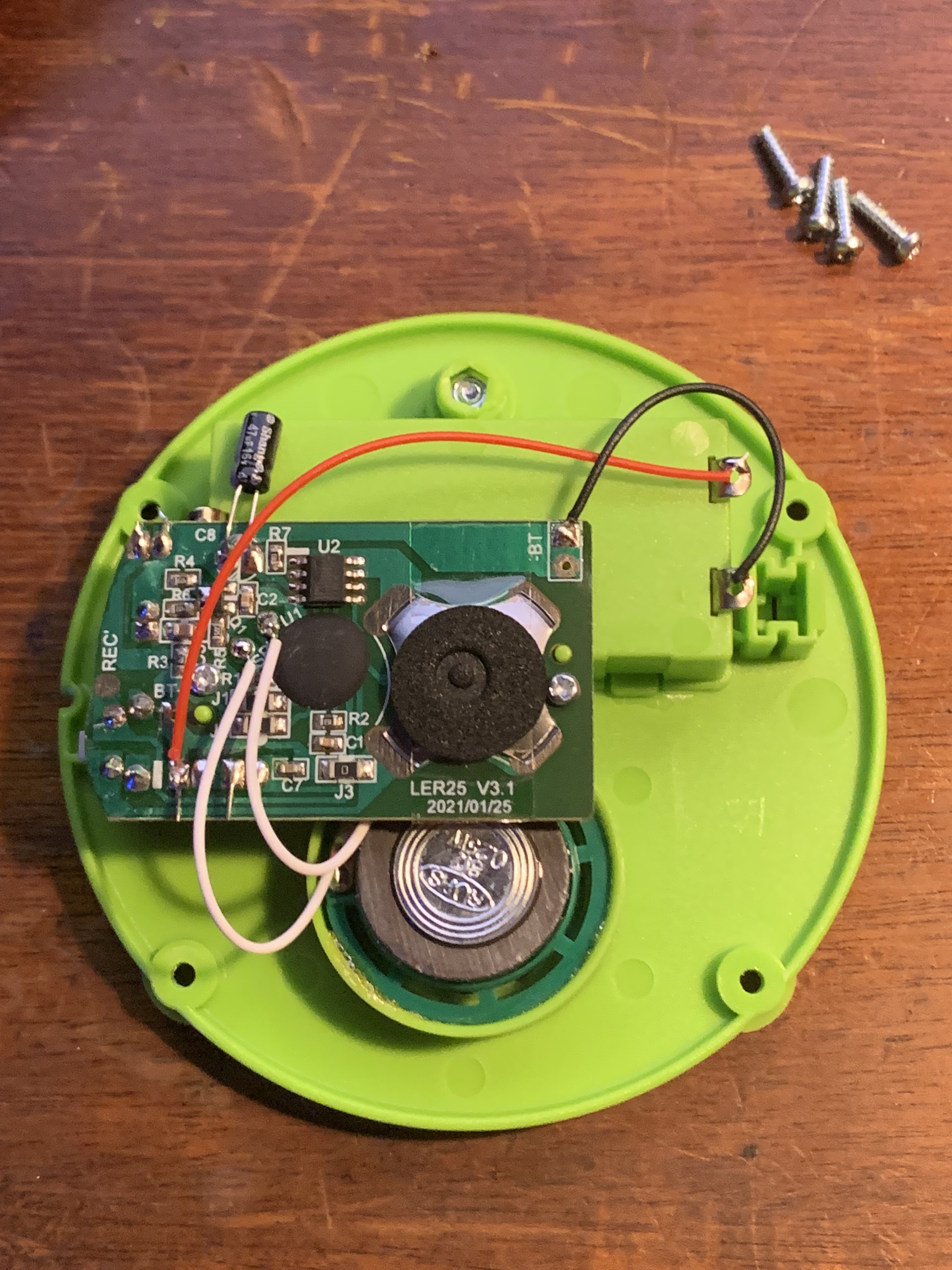
    The first and practically only thing you'll see when you open your button is the PCB. It holds the recording and playback circuitry and the switches for two buttons. You can also see the speaker peaking out from under the PCB. There will be four wires: two for power and two for the speaker. 

    The rest is empty space...

    ...and nature abhors a vacuum.

    Start by desoldering those four wires from the original PCB, leaving them attached to the (empty! It should be empty!) battery compartment and speaker. 

    Of the stuff attached to the original PCB, we really only care about the switches, and possibly the transistor. Remove the mic by clipping its leads, and save it for another project. Any other components on the board that seem useful to keep in your parts bin can be safely removed, too. If your PCB has a transistor you're planning on reusing, now might be a good time to desolder it.

    The easiest way to reuse the switches is to leave the original PCB in place so that it continues to mechanically hold the them in proper alignment with the case. This means we have to electrically disconnect these switches from the original circuit while leaving them physically attached. 

    Looking closely at the board, it should be easy to see the traces that connect each switch to the rest of the circuit. One side of each switch will be connected to ground, which is easy to identify because it's the largest area of the board. The other side will be connected to a thin trace that runs back to the original processor. Leave the ground side connected, then get something sharp.

    Knives Out

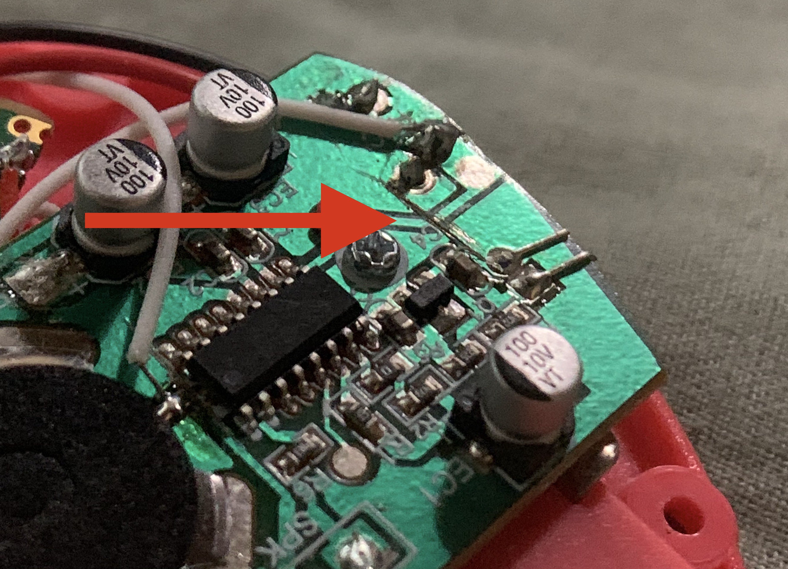
    Carefully cut through the thin traces with a sharp knife. If you make a mistake and multiple traces, that's ok! Nothing bad will happen at all. Here, you can see the trace leading to the under-mounted side switch, with the arrow pointing to where it has been cut. Also note how the cut extends well into the ground plane. This is fine. 

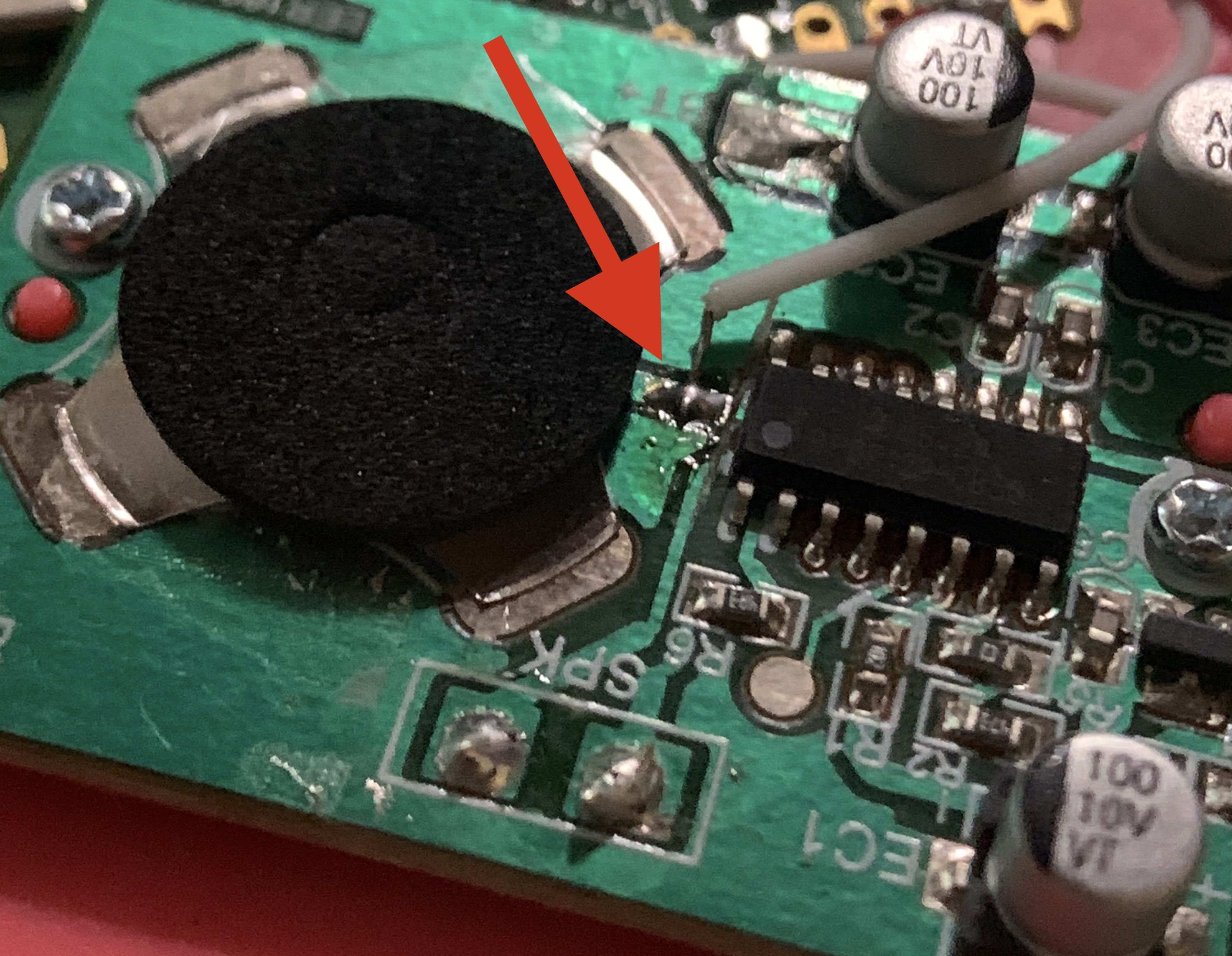
    Next we'll add a wire to each switch. Depending on what type of switches your button uses, it may be easy to solder a new wire right onto the pin of the button, as you can see in the photo above.  However, some buttons use dome switches that are surface mounted, meaning they have no pins:

    If you have a switch like this, you'll have locate the small trace that emerges from the center of the switch and scrape off its green coating to reveal the copper underneath. Then, you'll solder directly to the trace. Here's an example inside a button of mine, with a wire attached to the scraped and cut trace from the center of the dome switch:

    Leave the ground pins connected to ground. Next...

    We can rebuild him

    Now we can start hooking up our Pico W. As you can see in the diagram below,  just eight out of the forty pins available on the Pico W get hooked up to anything.

    • (please note the pins on the Pico W have been repositioned in this diagram for clarity)

    Mr. Transistor

    It's easiest to solder the transistor into place...

    Read more »

View all 10 project logs

  • 1
    Gathering

    The Positivity Pusher brings the most joy when it's built from scraps. Let's take a look at acquiring the parts needed.

    1. Pi Pico W - This is the most expensive part on the list at $6 new. It's also the most difficult to find used. 
      1. Big Online Retailers sometimes have used Picos for sale, but the price can be higher than buying new. 
      2. Local Sellers can be found, but it's less common.
      3. Your Own Drawer is probably the best place to find one. Maybe you have a Pico W leftover from another project. The Positivity Pusher uses very few GPIO, so even boards that are partially damaged (maybe with some burnt-out pins) can be repurposed. 
      4. Buying New is a last resort, but occasionally necessary. Fancy new technology isn't always available in the secondhand market. Skip amazon and get yours from an authorized reseller.  
    2. The Button - This is the easiest to find. The world is overflowing with plastic., there's no need to generate more waste for this li'l project. Used buttons are widely available, you can easily buy a four-pack from disappointed pet owners. 
    3. The Transistor - Many types of buttons have a suitable transistor right on their original PCB, though they are harder to work with due to their small size. If you don't have experience soldering surface mount components, it will probably be easier to use a bigger through-hole part. There are lots of extremely common transistors will work just fine. Some that I've personally tried include the 2N3904, C1815, C945 and even the the super common 2N2222. If you are a tinkerer, you probably already have one that will work. If not, skip the stores and salvage one from some broken electronics. Old stereos, PC power supplies and electric toys are all good potential sources. 
    1. The LED - I once bought a used bag full of fun color-cycling LEDs, so I chose that for my Pusher, but any common type will work. Other fun salvage sources for LEDs include toys, halloween decorations, etc. 
  • 2
    Hacking

    Your button will come with a fully functioning voice recorder on a small PCB. The enterprising hacker can remove this unit and reuse it elsewhere, but I chose to disconnect it and leave it in place because the PCB also holds the main button and the reset button in their correct position. In order to repurpose these buttons while leaving them in place, you'll have to cut the PCB traces that connect the buttons to the rest of that original circuit. See the full details here.

  • 3
    Wiring

    Connecting the Pico W to the original PCB is pretty easy! We use just three GPIO pins and a few other connections:

    1. Battery+ to Pico VSYS
    2. Battery- to Pico GND and original PCB GND
    3. Top Button Switch to Pico GPIO 0
    4. Transistor Base to Pico GPIO 1
    5. Transistor Emitter to Pico GND
    6. Transistor Collector to Speaker-
    7. Pico 3v3 to Speaker+
    8. LED+ to Pico GPIO 2

    See more details here

View all 5 instructions

Enjoy this project?

Share

Discussions

Marcrbarker wrote 12/21/2023 at 22:33 point

I see where you're coming from about the speaker driver. The source content volume varies a lot.  Speech only needs to 300 to 3k limit bandwidth at the transducer.  Distortion can be ok double-figures. The minimalist single transistor is virtually class c and normalises the signal. An audio IC amp is a non starter isn't any good with 2.x something volts supply. Can get more power in speaker by a H bridge driver from 2 npn/pnp pairs off two gpio.  Complementary signal while active and both drive low when silent. A possibility the gpio(s) could direct drive the transducer minus any transistor(s). 

  Are you sure? yes | no

Does this project spark your interest?

Become a member to follow this project and never miss any updates