Satisfied with the simulations performance, it's time to start making it for real.
Step one, schematic capture. I use KiCAD 6, and found that there was an update to version 7 during the middle of drawing. I was getting frustrated with how KiCAD deals with wires when dragging components around. During my search for a solution, I found that version 7 is the solution. Normally I don't update software in the middle of a project, but I took a calculated risk, and the transition was seamless. Score!
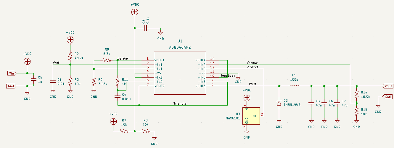
I made three minor changes (as compared to the LTSpice schematic) as I was drafting the schematic.
- The 1.25V reference was changed. The LT1389 is a 0.05% accurate part, and costs about $8 USD. So I changed it to a MAX6101, 0.4% accurate and only $1.48 USD.
- The output capacitance. Instead of a single component, I made room for three. This will give more flexibility during testing.
- I also added a bypass capacitor for the opamp package and input connection.
Discussions
Become a Hackaday.io Member
Create an account to leave a comment. Already have an account? Log In.