Here is where the rubber meets the road.
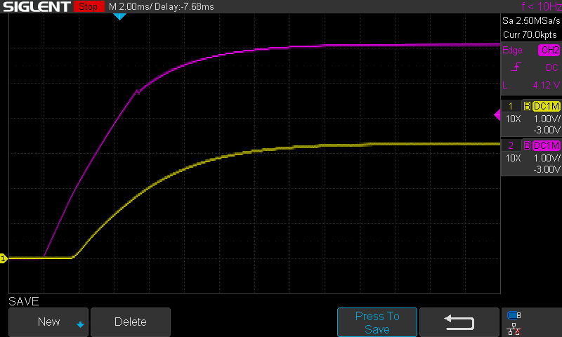
Purple is the input voltage 6V and yellow is the output voltage 3.3V
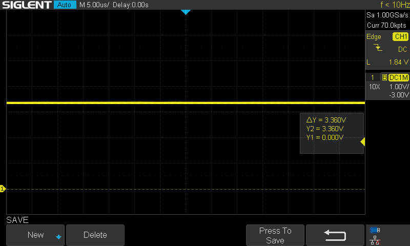
Looks pretty smooth and 3.36V, hits the target...
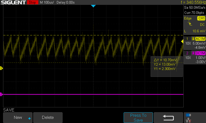
How about we zoom in a bit on that?
Put the scope into AC mode and zoomed in on the vertical scale. 10.7mVpp and I only have one 47uF output capacitor installed!
It's a switching regulator, so how efficient is it?
With a 68 ohm resistor as the load, that makes 3.3^2 / 68 = 160mW output power (3.3V / 68 = 48mA ).
The input power was between 6V * 94.8mA = 568mW and 11.3V * 68mA = 768mW
That puts the efficiency at a measly 160mW / 768mW * 100 = 20% to 160mW / 568mW * 100 = 28%
The opamp is getting quite toasty. A quick look at the datasheet indicates each of the 4 amps should only consume ~1.75mA max.
Something else is amiss...
Discussions
Become a Hackaday.io Member
Create an account to leave a comment. Already have an account? Log In.