First I started with the major building blocks of a buck regulator:
- Oscillator
- PWM
- Feedback
Poking around on the googles for opamp PWM, I ran across this great video series: Op-Amps, PWM
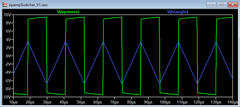
I quickly fired up LTSpice and simulated the circuits. It did work, but the waveforms were a little too off for my tastes. And, more importantly, it required a dual supply to operate.
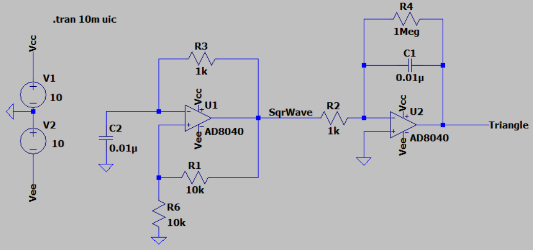
Basic operation is as follows:
The first opamp is a oscillator circuit used to make a square wave. The square wave is then integrated by the second opamp circuit, which produces a triangle wave.
The search continues...
Discussions
Become a Hackaday.io Member
Create an account to leave a comment. Already have an account? Log In.