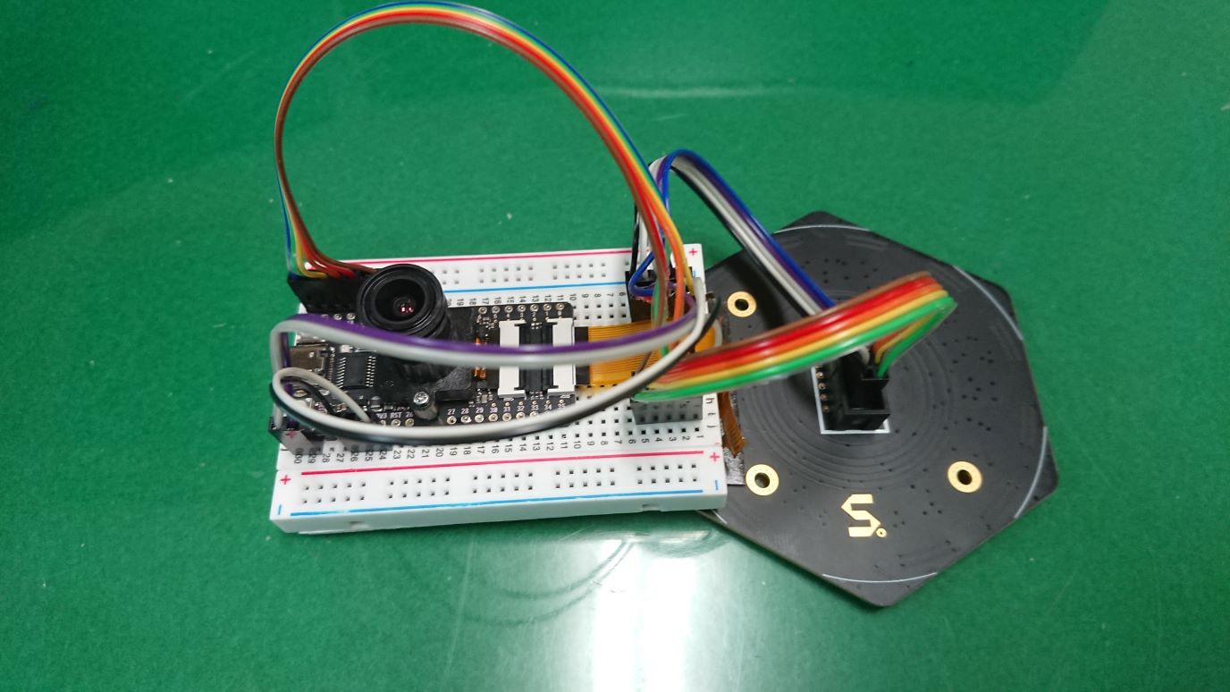
We will connect MaixBit and the microphone array. The correspondence between the pins to be connected and the GPIO is shown in the following table.
| MaixBit | Mic Array |
| PIN23 | MIC_D0 |
| PIN22 | MIC_D1 |
| PIN21 | MIC_D2 |
| PIN20 | MIC_D3 |
| PIN19 | MIC_WS |
| PIN18 | MIC_BCK |
| PIN17 | LED_CK |
| PIN15 | LED_DA |
| 3V3 | VIN |
| GND | GND |
We connected them with a jumper cable, and it looks like the picture below.

 AIRPOCKET
Discussions
Become a Hackaday.io Member
Create an account to leave a comment. Already have an account? Log In.