 Clyne
ClyneThe DSP add-on board has gone through three iterations since the project's beginnings. It first started with a proto-board and DIP-socket ICs, then moved to a slightly-buggy PCB with surface-mount components:
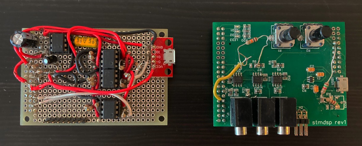
The PCB implementation used a high-precision resistor divided to create a voltage reference; however, poor value/power choices led to the resistors burning out. Resistor adjustments also had to be made to the amplifiers to reduce some major signal noise. Additionally, the three status LEDs are facing south rather than up, a mistake in component selection.
The following revision (the current blue-PCB board) added a 3.3V reference, lower-noise operational amplifiers, and some signal filtering RC circuits. A couple of minor edits to this board has resulted in a reliable, high-quality add-on board.
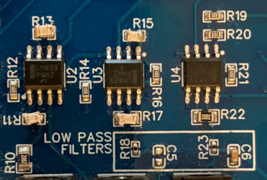
R11, R13, R15, and R17 have 220pF capacitors stacked on top to reduce high-frequency noise in the input and output signals. C5 was removed as the RC filter was not working as expected, instead distorted the signal.
A final, fourth iteration is planned to build in these edits and produce a board that is ready for larger production and distributing to other users. Designing this iteration will also see a change in CAD software: the previous designs were done with EasyEDA, an online and proprietary solution linked to JLCPCB. This was chosen to simplify the production process, but is not ideal for more mature, open-source projects.
So, this iteration will be designed with KiCAD. This also means that the KiCAD project files can be added to the project's repositories, making it easier for others to work with hardware "source".
Discussions
Become a Hackaday.io Member
Create an account to leave a comment. Already have an account? Log In.