 Clyne
ClyneRealizing the hardware and software for DSP PAW is central to the project's success; however, examples of algorithm implementations will be essential for making DSP PAW an adaptable solution. So, I've begun work on some guides that walk through writing and analyzing some common algorithms. As they're finished, these guides will get uploaded or linked to the project's code repository. Below is a kind of "rough draft" of what I would include in a guide; in the future, I will most likely post about newly available guides rather than writing them in these logs.
To start, I will show the implementation of low- and high-pass filters. These filters block out high and low frequencies respectively, and so their effect and behavior are easily observed. I chose to keep these implementations relatively simple by using first-order infinite impulse response (IIR) filters. As much as I would like to get into the DSP theory behind IIR filters, it will be best for now if I leave that to the proven educational materials found elsewhere online.
In short, both the low- and high-pass filters follow this formula:
y[n] = b0 * x[n] + b1 * x[n - 1] - a1 * y[n - 1]
...which is conveniently already valid C++ code. The coefficients a1, b0, and b1 can be calculated into variables given specified cut-off (Fc) and sampling (Fs) frequencies:
constexpr float Fc = 1000;
constexpr float Fs = 32000;


constexpr float Omega = 2 * 3.14159f * Fc / Fs;
constexpr float K = tan(Omega / 2.f);
constexpr float alpha = 1 + K;

constexpr float a1 = -(1 - K) / alpha;

// For low-pass filtering:
constexpr float b0 = K / alpha;
constexpr float b1 = b0;

// For high-pass:
constexpr float b0 = 1 / alpha;
constexpr float b1 = -b0;
By using the constexpr keyword, these values are calculated at compile-time, reducing execution time. Unfortunately, the above code will have an issue with the current DSP PAW software: a custom tan() implementation that calls into the core firmware will prevent K's compile-time evaluation. This can be fixed, but for now K will need to be calculated by hand and typed in.
One more requirement of these filters is that the sample data needs to be centered at zero. So, a short "normalization" function is written to convert a sample's 0 through 4095 integer value into a decimal -1.0 to 1.0 range. It may be possible to integrate this transformation into the filter as a performance optimization.
inline float N(Sample s) {
    return (s - 2048) / 2048.f;
}
Finally, we write the iterative loop that calculates each output sample. A buffer is defined to store the output since the input samples need to be preserved for calculation. If that were not the case, the sample buffer passed into process_data could be reused:
Sample* process_data(Samples x) {
	static Samples y;

	for (int n = 1; n < SIZE; ++n) {
		float y_n = b0 * N(x[n]) + b1 * N(x[n - 1]) - a1 * N(y[n - 1]);
		y[n] = (y_n + 1.f) * 2048; // return to 0-4095 range
	}

	return y;
}
To test these filters, I used an Analog Discovery 2. The software for this device is advanced, and provided me with a sweeped-frequency signal and a spectrogram to capture the filters' frequency responses. Both of these features could (and should) be built into DSP PAW. For now, testing without external hardware could have been done by loading the on-board signal generator with a sine wave (or perhaps low- and high-frequency sine waves added together) and observing the output's attenuation/form through the signal visualizer.
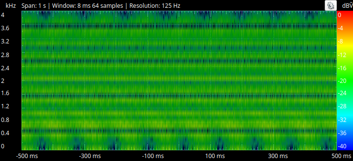
Here is the spectrogram with no filter running. All frequencies in the sweep are showing up in green:
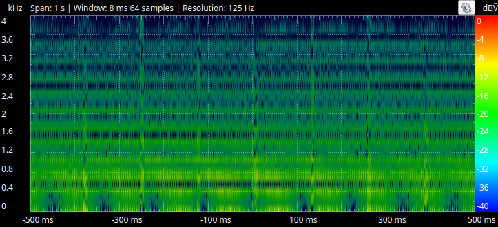
With the implemented low-pass filter, attenuation of frequencies higher than 1kHz can be seen. Due to the nature of first-order IIR filtering, the attenuation is gradual and not "strong" at the specified cut-off.
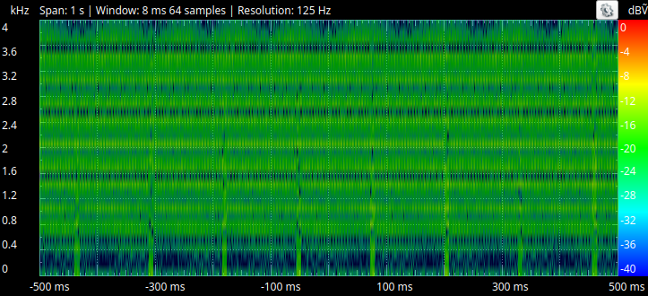
The implemented high-pass filter passes through the frequencies beyond 1kHz, with attenuation below 1kHz clearly observable. Again, the cut-off's strength and spread is fairly weak.
As an extension to this algorithm, it is possible to control the targeted cut-off frequency at run-time with one of the add-on board's knobs. This is done by defining the alpha parameter as a function of the knob's position. For low-pass, the resulting alpha must be greater than 1, while for high-pass it needs to be less than 1. The K parameter must then be redefined in terms of alpha:
float alpha = param1() / 2047.f + 1.01f; // Low-pass: 1 < alpha <= 3
float K = alpha - 1.f;
(One could also apply these filters to an audio signal -- the effect will be noticeable in recordings that include significant treble and/or bass.)
Discussions
Become a Hackaday.io Member
Create an account to leave a comment. Already have an account? Log In.