Close
0%
0%

DC Input Protector - Level Shifter

Real world DC logic signal conversion to common microprocessor levels.

Similar projects worth following
Switchgear signals require level shifting as well as protection from inductive load switching spikes to interface with fast acting data acquisition devices. This circuit will auto-range a signal from common relay logic levels of 24VDC up to 48VDC levels commonly found in industrial electrical switchgear, allowing a DAQ or microcontroller to record the sequence of events. Isolation will protect the monitoring circuit from the inductive load switching spikes such as breaker close and trip solenoids. This will be a modern day replacement of a "first trip" or "tell circuit" hard wired relay circuit that can interface with common DC coil voltages of relays found in industrial switchgear.

The preliminary design is completed. A breadboard is done and the circuit has had an initial test.

Some notes about the project:

I wanted to utilize analog devices that I had on-hand, kind of a walk down memory lane of my electronics hobby and education. For the breadboard circuit, I found a 12V zener diode that was still in the Archer (Radioshack) package. I found metal can RCA op-amps that I had from a rummage sale of a retired Hewlett Packard employee. There is a wire-wound resistor that my brother and I had harvested from a TV set in the 1970's.

I only found one link to the pinout of the metal-can op-amps. It was a different brand, but the pinout turned out to be the same.

If I am comparing signals in the real-world, as long as the delays are the same, I can find which signal occurred first. The delay of the circuit is not relevant to the history of events.

  • Ideas for improvement/testing

    Doug05/23/2023 at 19:57 0 comments

    1. Measure the voltage dividers and adjust for a 5V output.
    2. Connect to a digital microprocessor and test.
    3. Build a second circuit with the op-amps powered from a lab source. Measure the Vout signal from both circuits to find the delay of the op-amps startup.
    4. The Vce of the 2N3904 is being exceeded. Substitue a suitable replacement with higher Vce rating.
    5. Add transient filtering on the input.
    6. Develop a circuit that could handle 125VDC. There is not much switchgear with 125VDC logic signals, but there are some breaker solenoids that operate at that level. It would be handy to be able to bring those signals in for an event history also.
    7. Design a final output stage with isolation. This could be done with optical isolation or perhaps with some of the newer magnetic isolation ICs developed for EV vehicles.

  • Prototyping

    Doug05/23/2023 at 18:08 0 comments

    Prototyping:

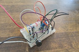
    I built the prototype on a protoboard so I could easily substitute components and make changes. I did not build the entire circuit at once and "swing for the fences", e.g. powering it on and hoping I didn't release any smoke. I built it up in stages, testing as it was built.

    1. I built the resistor divider/Zener circuit and tested the resulting voltage level.

    2. I added the unity gain amplifier which provides isolation and the voltage reference to the 2nd op-amp.

    3. I added the output stage with the voltage divider feedback circuit.

View all 2 project logs

Enjoy this project?

Share

Discussions

Similar Projects

Does this project spark your interest?

Become a member to follow this project and never miss any updates