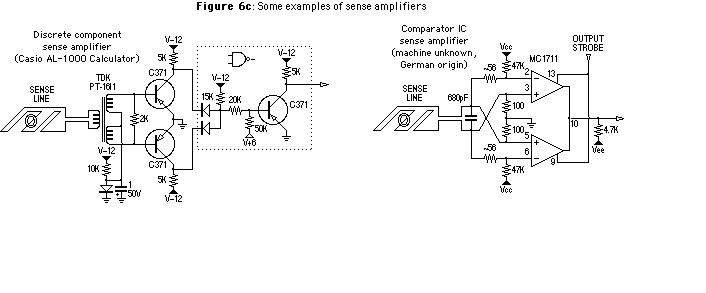
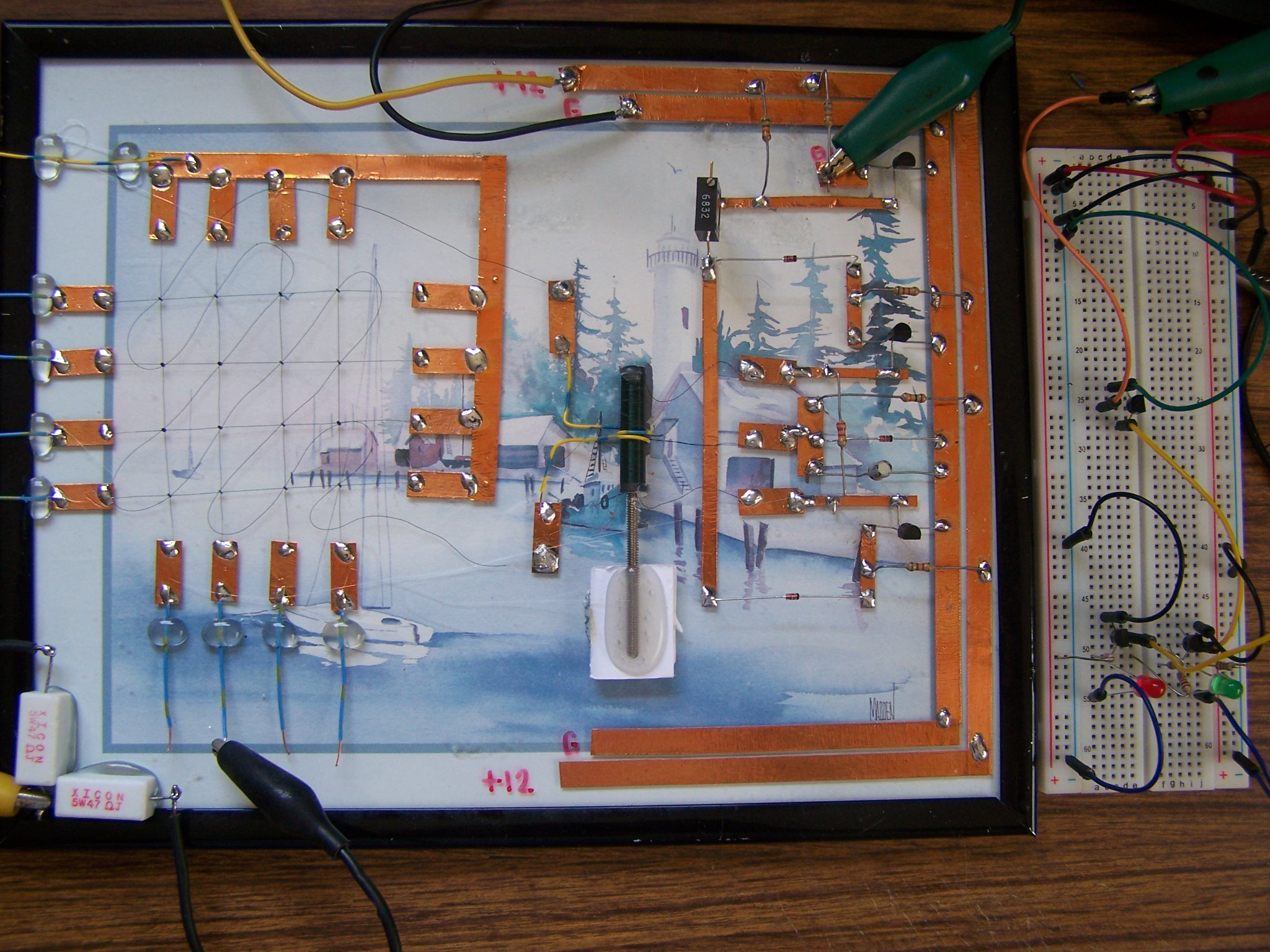
The very basic Sense Read circuit is directly from the Casio AL-1000 calculator. The only issue I had was the Sense Transformer as I could not find any information on the TDK part called out so I just took a wild guess and wound my own transformer. I also used NPN transistors and reversed the voltage polarity but other wise the same functional circuit. There are quite a few good articles on the internet to help learn how Magnetic Core Memory works and what is required. This is the Read portion of a three wire system where the memory Read is destructive and once a bit is read as a 1, the core flips to the reverse magnetic orientation which requires the bit to be rewriten to its prior state. In 1965 IBM patented a 4 wire non-destructive system but the timing is much too complex for this current experiment.


The voltage on the X and Y address wires is currently about 13.5 Volts @ 270 mA per active wire using a pair of 47 Ohm 5 Watt resistors, one for each axis.
I also used BC-549 NPN transistors and reversed the voltage polarity. The NAND gate circuit can be what ever you want to use.
The experimental board on the right is a basic transistor switch and a SR-Latch.
 Dr. Cockroach
Discussions
Become a Hackaday.io Member
Create an account to leave a comment. Already have an account? Log In.