[Feb 03]
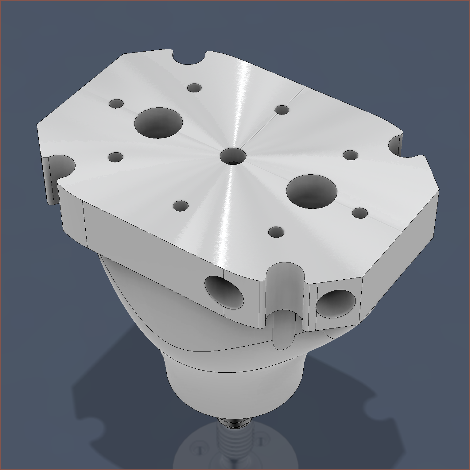
So I just wanted to see some stats on what a fully tweaked design that I suggested in the previous log would look like (and cost) so I spent the past 2 hours doing just that. The idea is that the top face (shown above) and the bottom face of the M6 is lathed down so that it's much smoother than the raw print, and then a plate is screwed into the top which itself contains threaded holes. Unlike what has been experienced so far, these threads will be able to completely go through the material without imperfections.
When everything is put together, it looks like this:
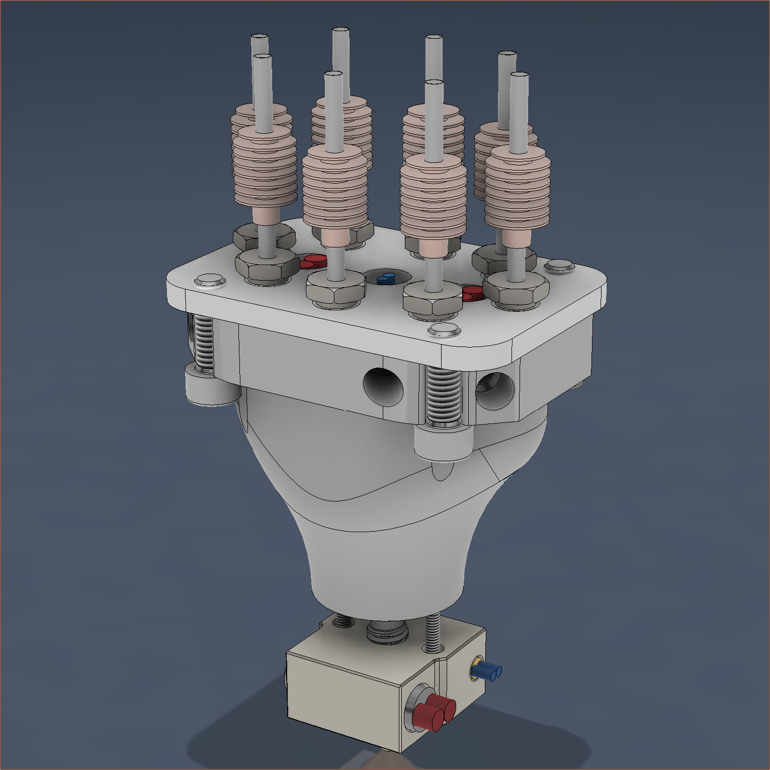
My only worry is that deckingman used much more screws to clamp it down in his design, and the clamping plate is probably at least twice as thick too.
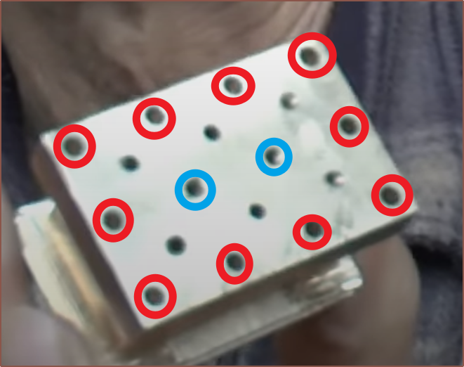
The red marked ones go through (like in my design) and the blue marked ones are tapped into the block.
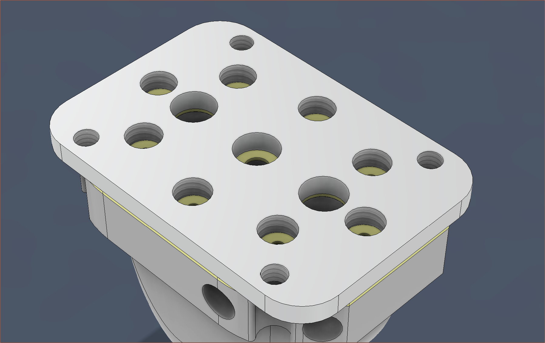
I'm wondering if a cut sheet of PTFE / silicone / kapton could be used as a gasket seal, potentially even eliminating the need for the polishing of the top face:
Wait a second...
(Mentally) Computing a pressurised system.
Simulation...
successful.
Isn't this precisely what gaskets are used for in other industries? I guess a gasket would be hard/tedious to implement in a normal 1-in-1-out hotend, so that's why it's not used and a metal-on-metal contact is relied upon. It seems that a 0.5mm or 0.8mm gasket would be fine:
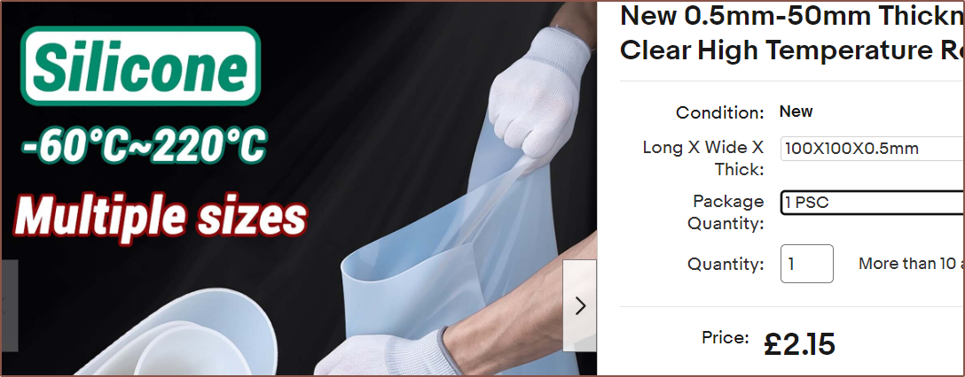
I presume that I can figure out some kind of mounting strategy by adding threads in the clamp plate for some titanium bolts.

If there are no surprises, I expect the print cost itself to be around about $60 and the full price to be in the $80 - $100 (£64 - £80) range.
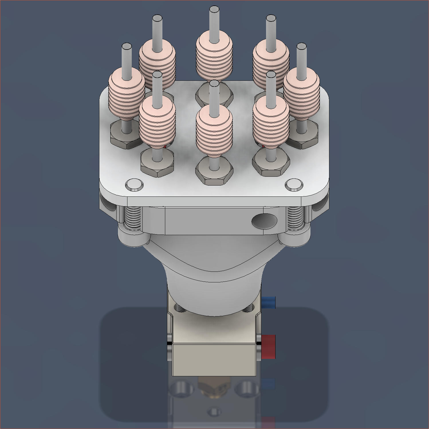
This should solve all the expected issues other than the surface roughness of the print itself. I don't know if 1.25mm is going to be wide enough for the minor channels nor if 0.8mm between the knife-edge and inner tube (that the thermistor goes into) will be enough space. There's also the question on if I can actually just grub-block unused inputs or if that runs the risk that those paths could get permanently blocked with charred filament.
[Feb 04]
I've spaced the gap between the knife edge and the internal cylinder from 0.8mm to 1.0mm just to give the least chance of powder imperfections affecting the output. I've also corrected the heatbreak model and given it a much more copper-looking tint:
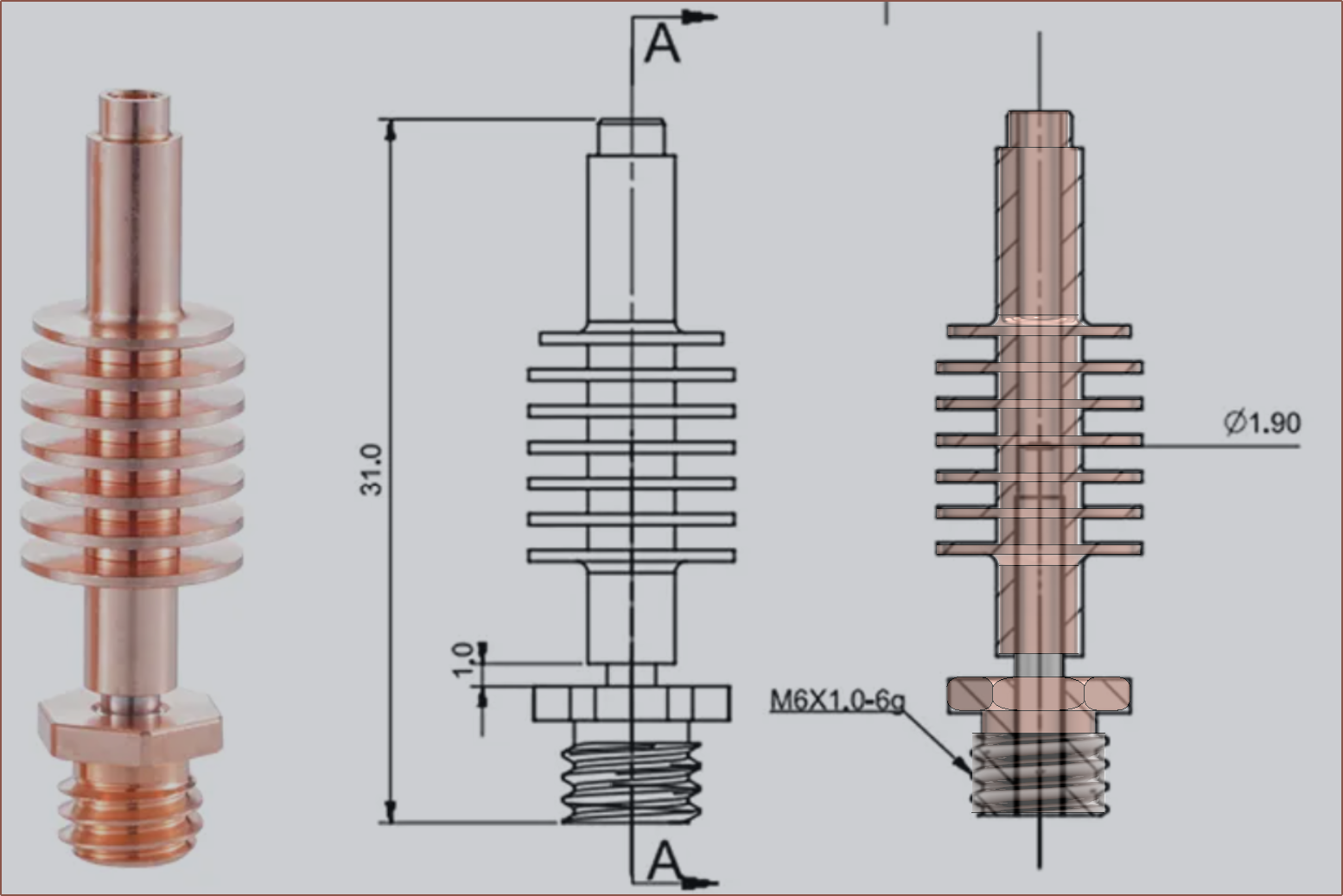
As for the mounting situation, I'm planning to mount it facing backwards (as it's unlikely that I'd need to touch the cartridge grub screws) and use grub screws that clamp onto the 3.5mm tops of the diagonal 4 heatsinks. The 2.65mm topmost part should be able to sit inside the compression fitting's 3.2mm bottom hole and there would be little reason why said fitting would need to be expanded so that the bowden could come though.
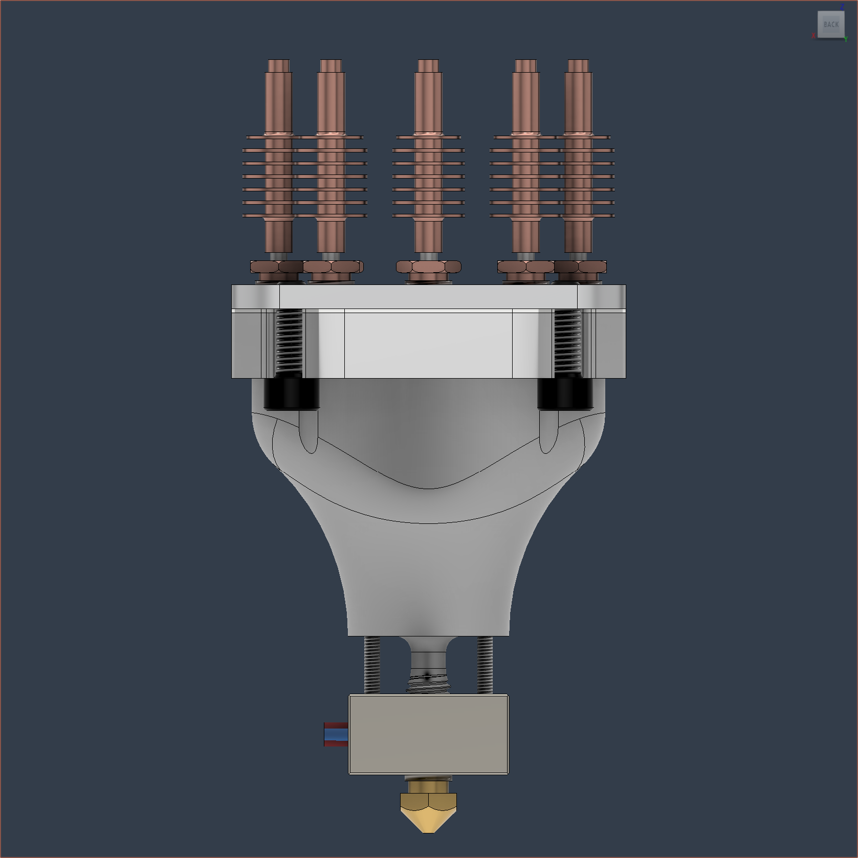
I also did some research on the seal and the recommendation is the thinner the better.
The entire printed part PCBWay price is $78.17 (£61.95) with standard global shipping.
This design should also mean that only the easier-to-make clamp plate would have to be remade if the threads are misaligned or need a design change.
 kelvinA
Discussions
Become a Hackaday.io Member
Create an account to leave a comment. Already have an account? Log In.