 kelvinA
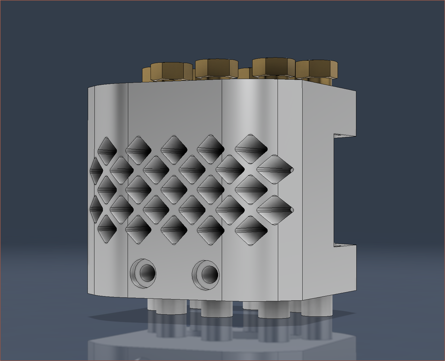
So I've been thinking of how I was going to do this for a while, such as the geometry and feature order. The first thing I did was research how heatsinks have been designed by others, and what I could gather is that they a) make sure that it's printable geometry, b) they usually use lattices and c) add fillets to prevent sharp edges.
Part a sounds obvious, but it means that I'm unlikely to be able to use a standard hotend design (see below) considering that I intend for PCBway to print upside-down.
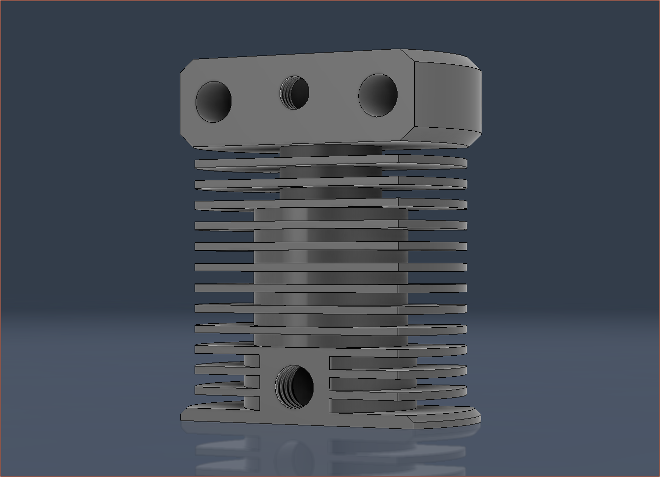
Just like with an FDM printer, those overhangs wouldn't print. If anything, DMLS is even less tolerant of overhangs than FDM.
But other than that limitation, it doesn't seem like there's any general best-practice for this kind of thing short of CFD so I had to come up with my own solution. Well, I finally looked into designing something after days occasionally thinking about it and the idea I had come up with was reduced to atoms when I got here:
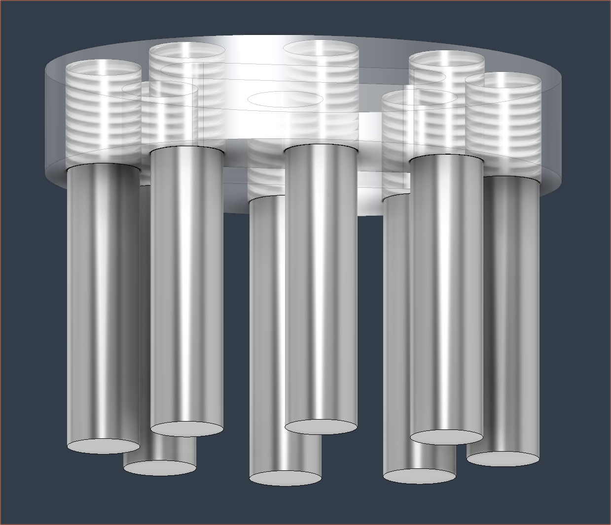
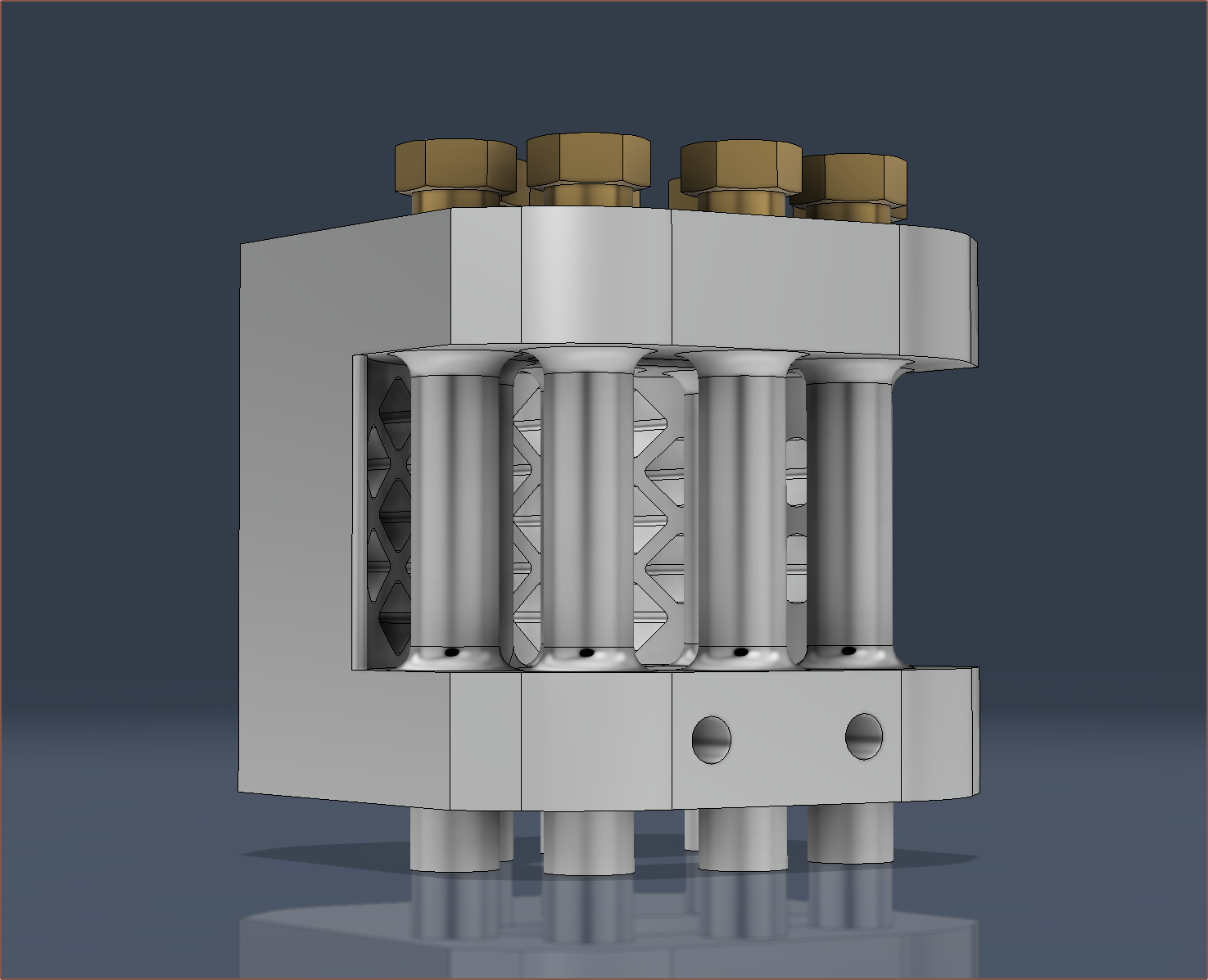
Turns out that these tubes for the PTFE are so wide that the idea I had would mean that there would be almost no fin surface area.
The solution? Designing the heatsink infront of the tubes, similar to the metal part of this BMG extruder:
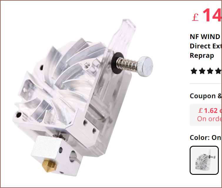
For the most part, if I remember correctly, air goes around cylinders relatively uninterrupted, so hopefully the airflow is decent.
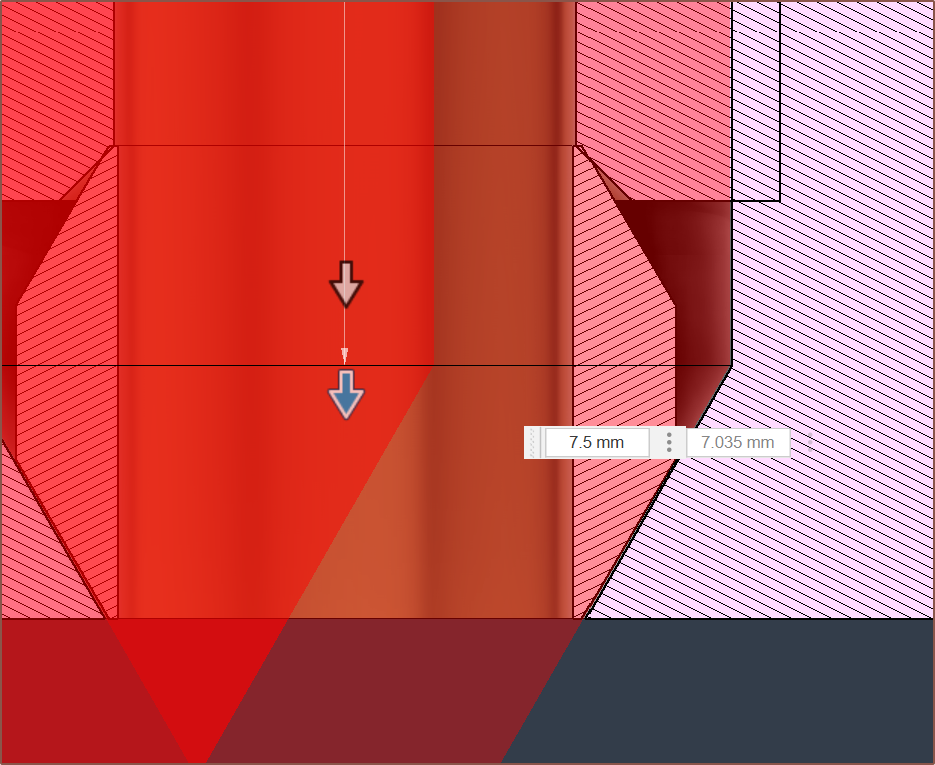 For the PTFE compression fittings, I've used the Fusion360 hole feature, with a bottom angle of 60 degrees, thread depth of 6.5mm, total depth of 7.5mm and thread of 8x1.
 I also increased the walls around the threads to follow this recommendation:

Discussions
Become a Hackaday.io Member
Create an account to leave a comment. Already have an account? Log In.