I've fixed the levelling Z height and determined that the PETG sticks at 84C instead of 72C on my machine. I tried a 1 : 1 mix of black and magenta but that just made a colour similar to "#222" when compared to the all-black clip I printed with R0. Unexpectedly, the black channel choked and so I was able to issue an M165 to change the mix to 1 : 1 white/magenta. Noticing how fast the colour changed, I wanted to see if I used yellow instead of white.
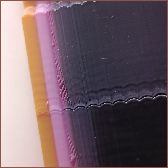
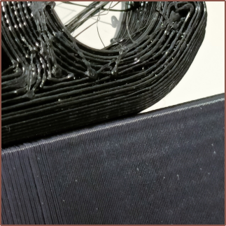
Part of the reason I'm using 4-bit-per-channel colour is partially a form of "rounding", since I don't have the tools to precisely measure colour and physical objects will look different based on the kind of light that hits it anyway (the "mint" filament looks closer to cyan under a daylight-white light source). My estimate for these 2 new colours is "#C9B" for the pink and "#A74" for the grapefruit-yellow.
As for actually calibrating input shaping, it was inconclusive. I also noticed slow-growing blobs from the Coaxial8or.
I decided to use the zeta x and y gcodes instead to calibrate each axis individually. It was inconclusive on the first few rounds as I had set the speed to 30% to test the waters. I found that I got the pattern to reliably stick at 0.2mm layer height and 1.5x extrusion multiplier, as well as limiting the test frequency to 36Hz.

While printing, I could see and hear when the Y axis hit the resonant frequency. The issue was that it seemed like it was in 2 different points depending if the resonant frequency was increasing or decreasing.
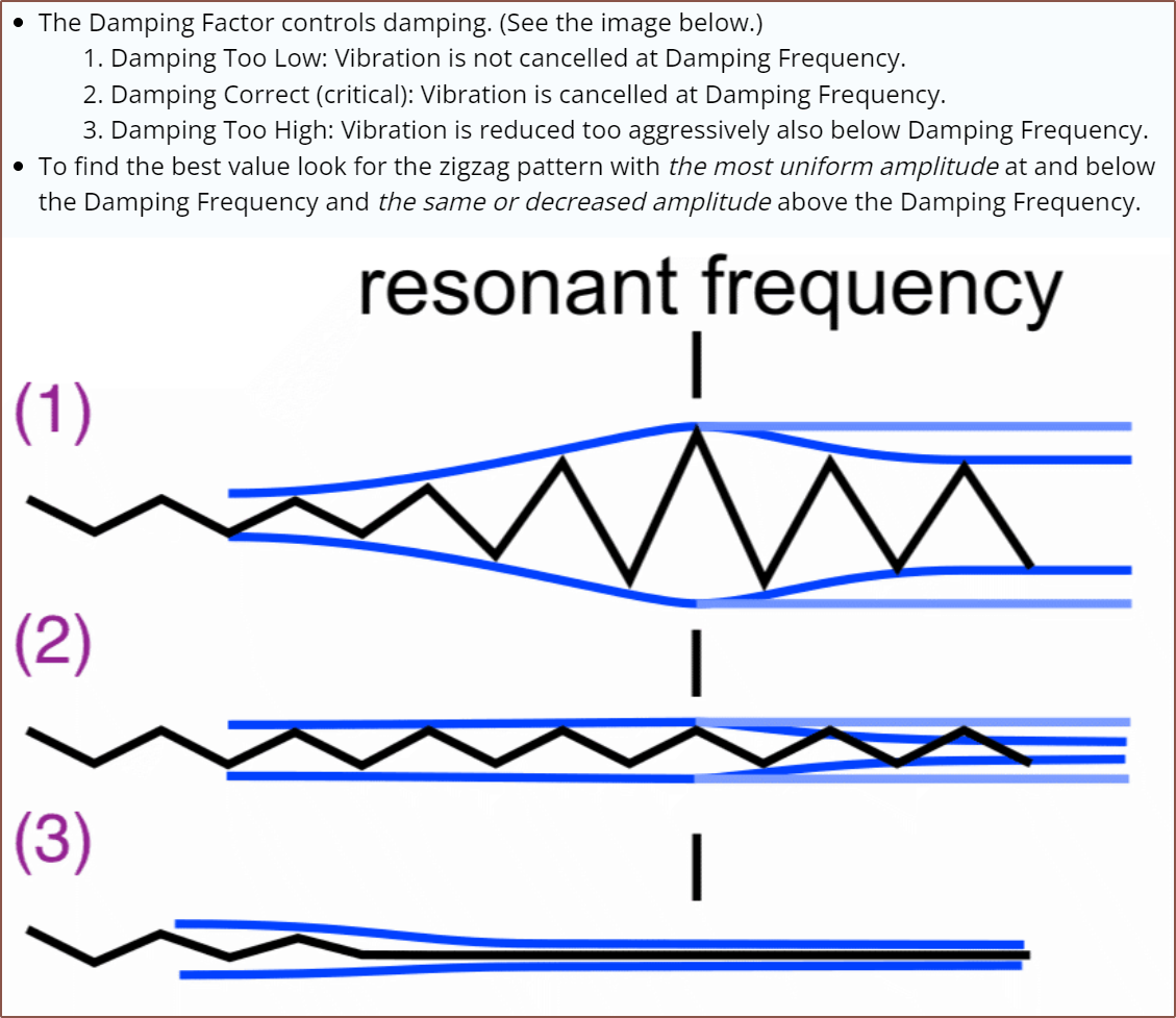 As you can see from Marlin's diagram, It seems that I'm looking for the most "jagged" looking line throughout and the resonant frequency is the largest V or ∧. Unfortunately, the test pattern doesn't make that easy. I eventually came to the hypothesis that, in reality, the sharp point will actually curl up as the nozzle moves back towards the centerline. Taking the spring steel off the bed, I angled it around to see that one sharp point in a few of the lines was slightly raised compared to others, and I took that as the resonant frequency (highlighted in green below). I also thin 0.7 zeta looks the closest to the ideal (highlighted in blue below):
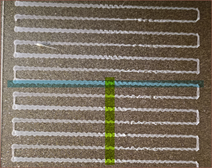
I do wish that the pattern could be clipped and scaled another 2X (thus 4mm is 1Hz, starting from 10Hz for example), since the really low frequencies overextrude. Another idea would be an option to print an S shape, 1-layer-thick raft so that the test was less susceptible to bed adhesion issues, but that may decrease contrast of the pattern.
The X axis was even harder to determine and it's possible that I only barely caught it in the 36Hz window:
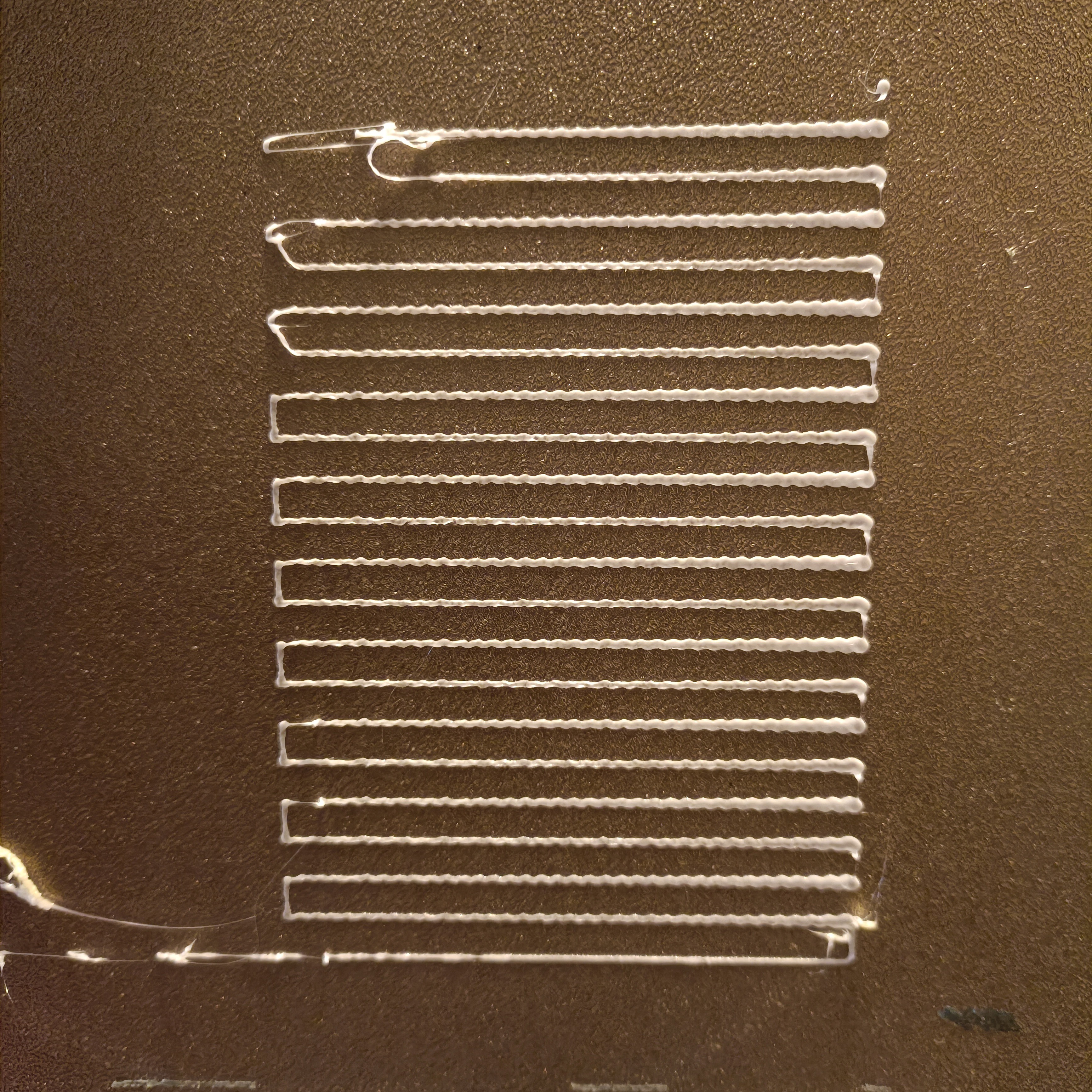
My results from this test:
#if ENABLED(INPUT_SHAPING_X)
    #define SHAPING_FREQ_X  31.6
    #define SHAPING_ZETA_X   0.6
  #endif
  #if ENABLED(INPUT_SHAPING_Y)
    #define SHAPING_FREQ_Y  18.3
    #define SHAPING_ZETA_Y   0.7
[...]
#define SHAPING_MIN_FREQ  15.0     // Default is 20 and line commented out
I decided to round up the zeta factor to the nearest 0.1
 kelvinA
Discussions
Become a Hackaday.io Member
Create an account to leave a comment. Already have an account? Log In.