Partially to answer @Trovoski, but mainly so that I can have confidence in the coaxialiser simulations before I spend another £55 (engineer quote + shipping) on the 3rd heatblock revision, I've been looking at the cross section of the extrusion.
0.6mm nozzle
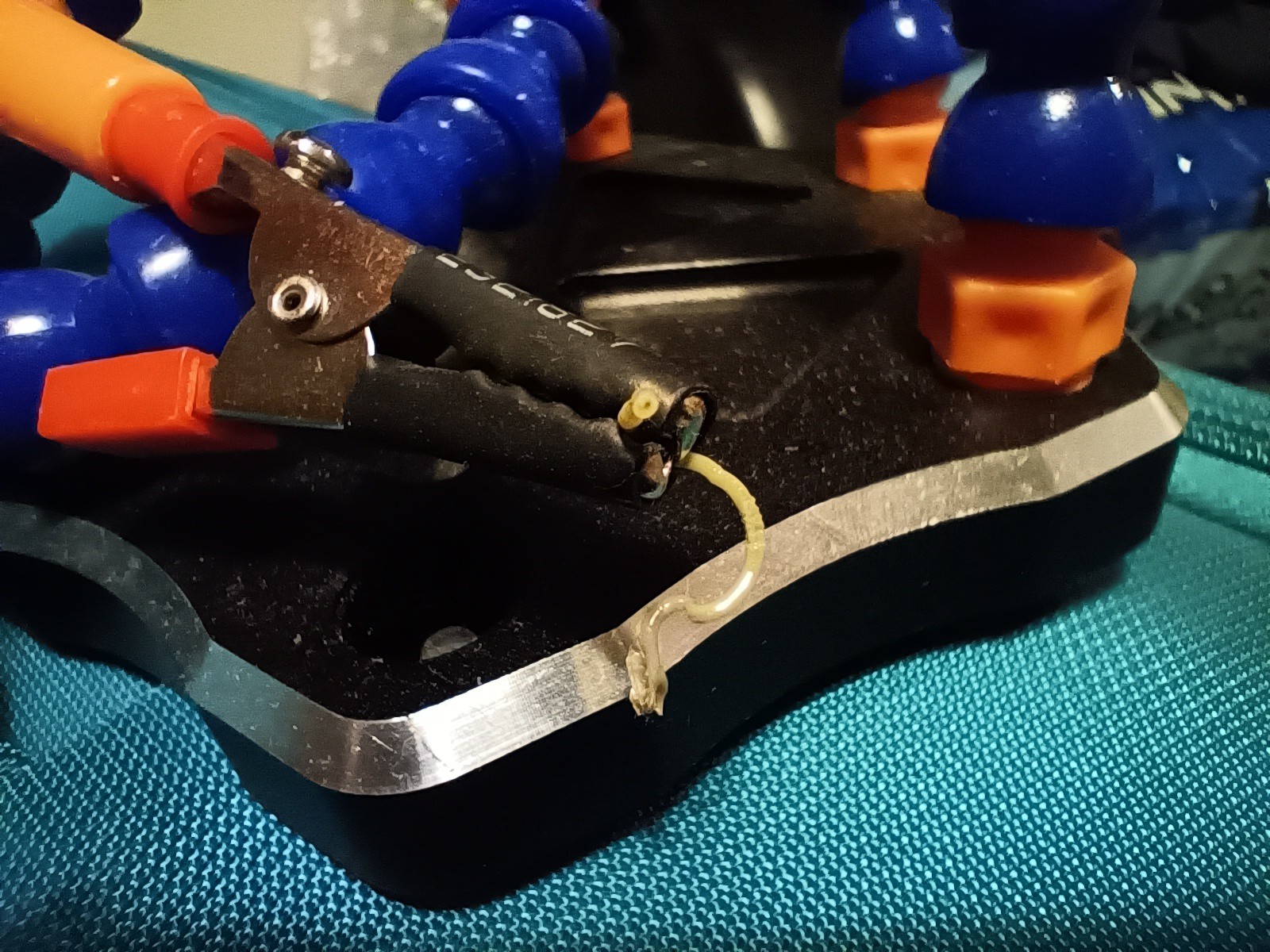
While it's too small to see the shape of the inner core, I was able to at least see that there was an inner core with a 0.6mm nozzle. I did yellow : black and cyan : copper as a 2 : 1 mix and then cut the extrusion with the PTFE cutter.
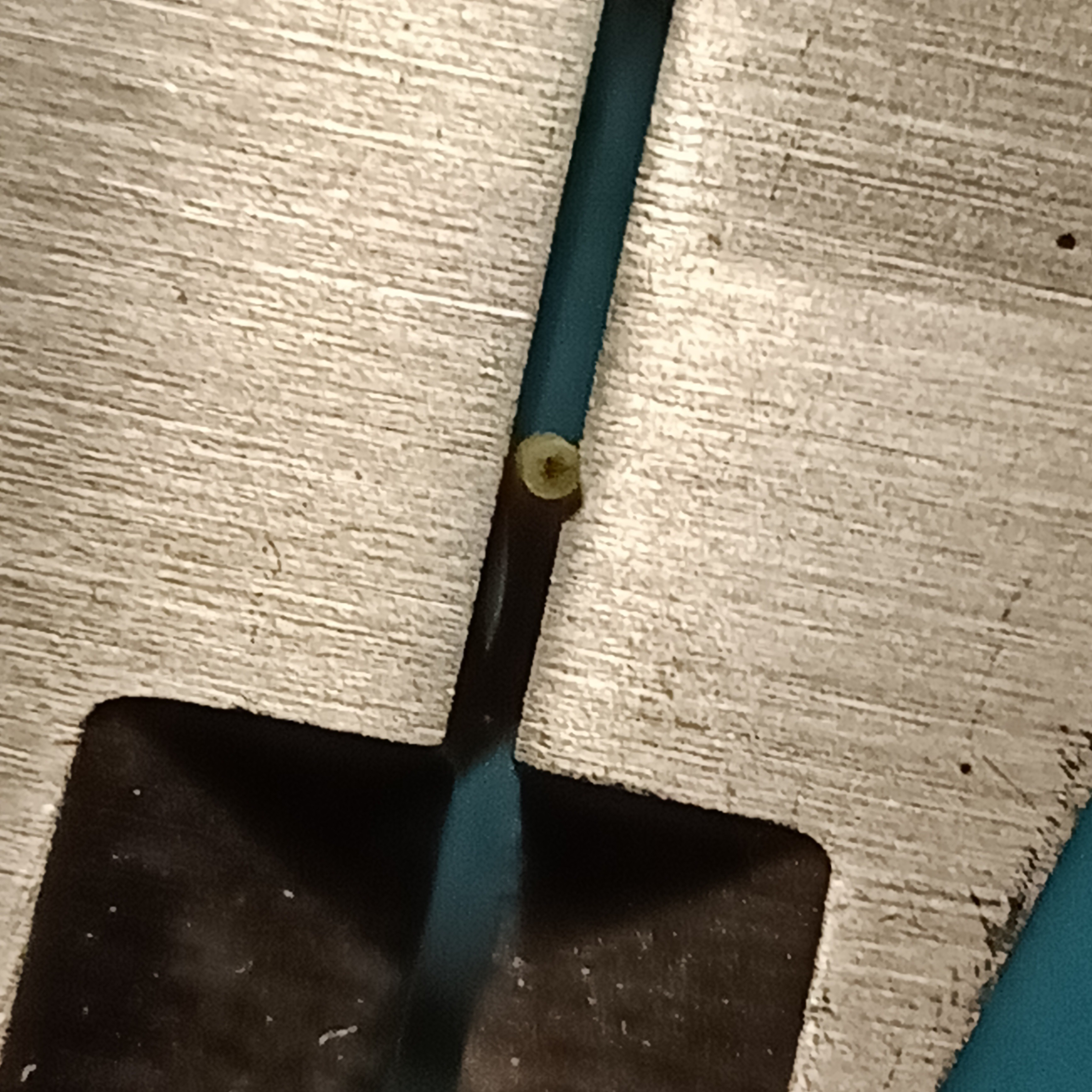
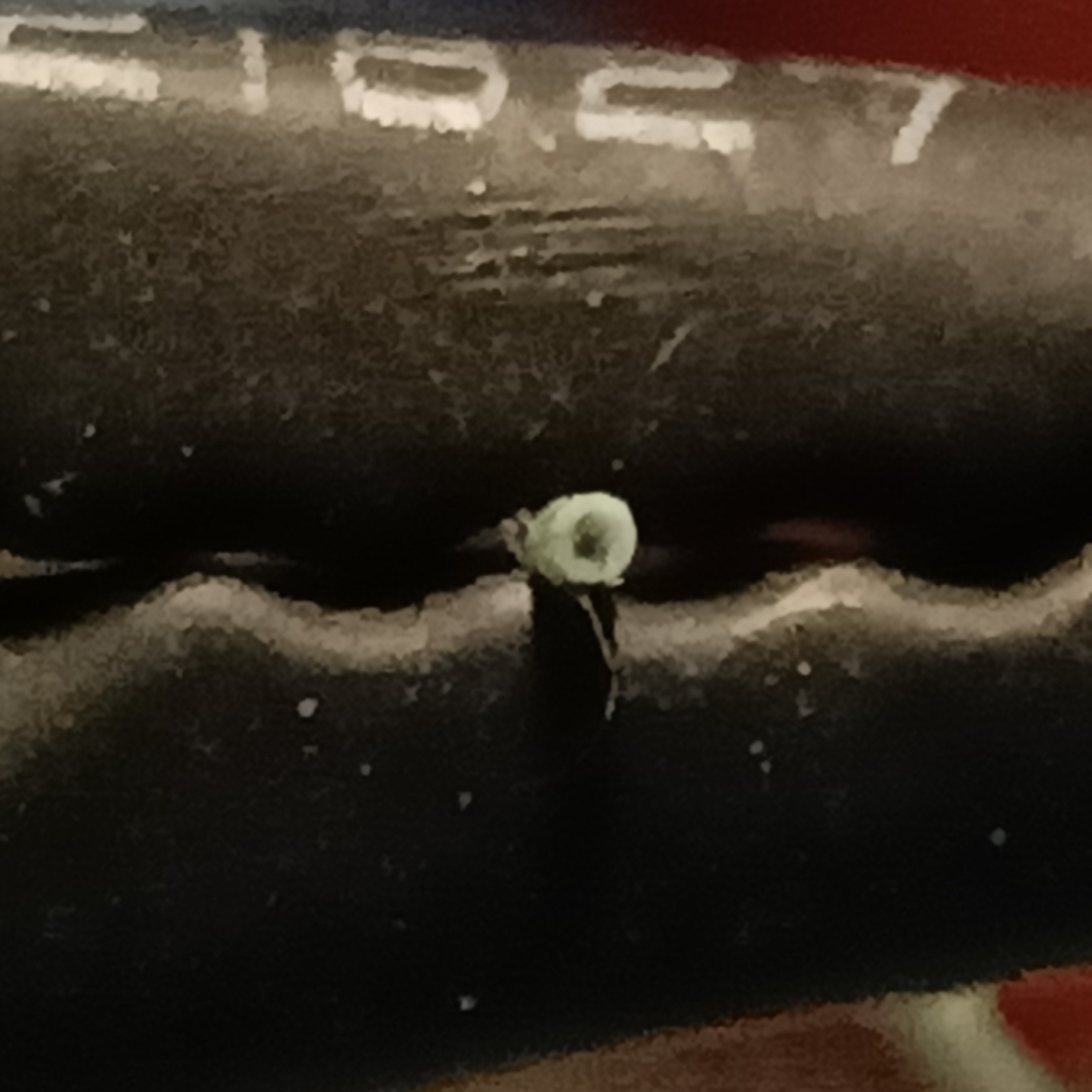
With the cyan/copper extrusion, I could also see a streak of copper on the side. This seems to be disconnected from the inner core. I suspect that this is residual copper that has clinged to the walls of the internal channels when cyan came through.
Nozzleless
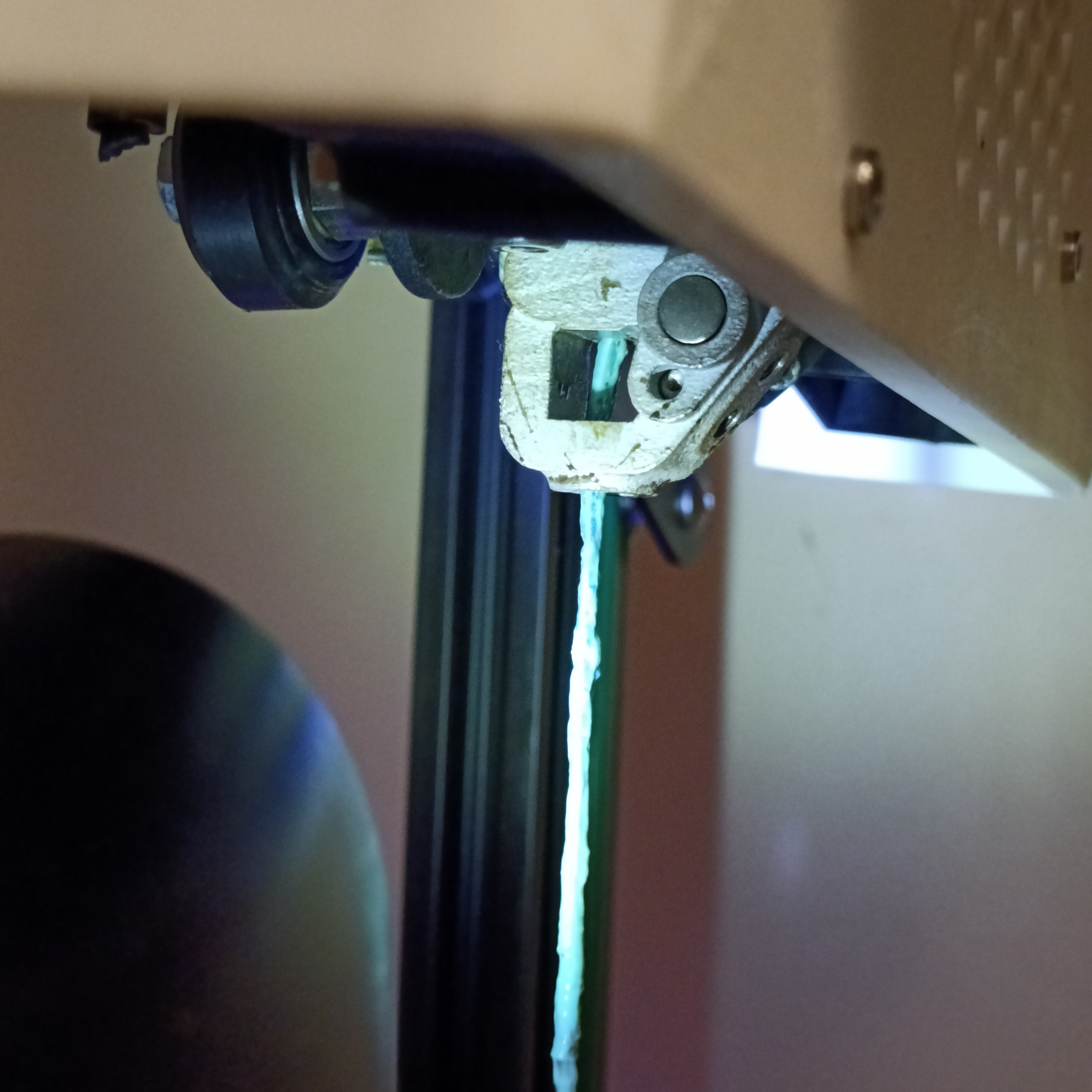
Unfortunately, the extrusion was very uneven and bumpy when I removed the nozzle. I hoped that it would just be a smooth, 2mm-or-so filament, but it actually came out 2.05 x 2.60mm. The good news was that I was at least able to see the transition from cyan to transparent-blue:


As you can see, one side transitions faster than the other.
1.2mm nozzle
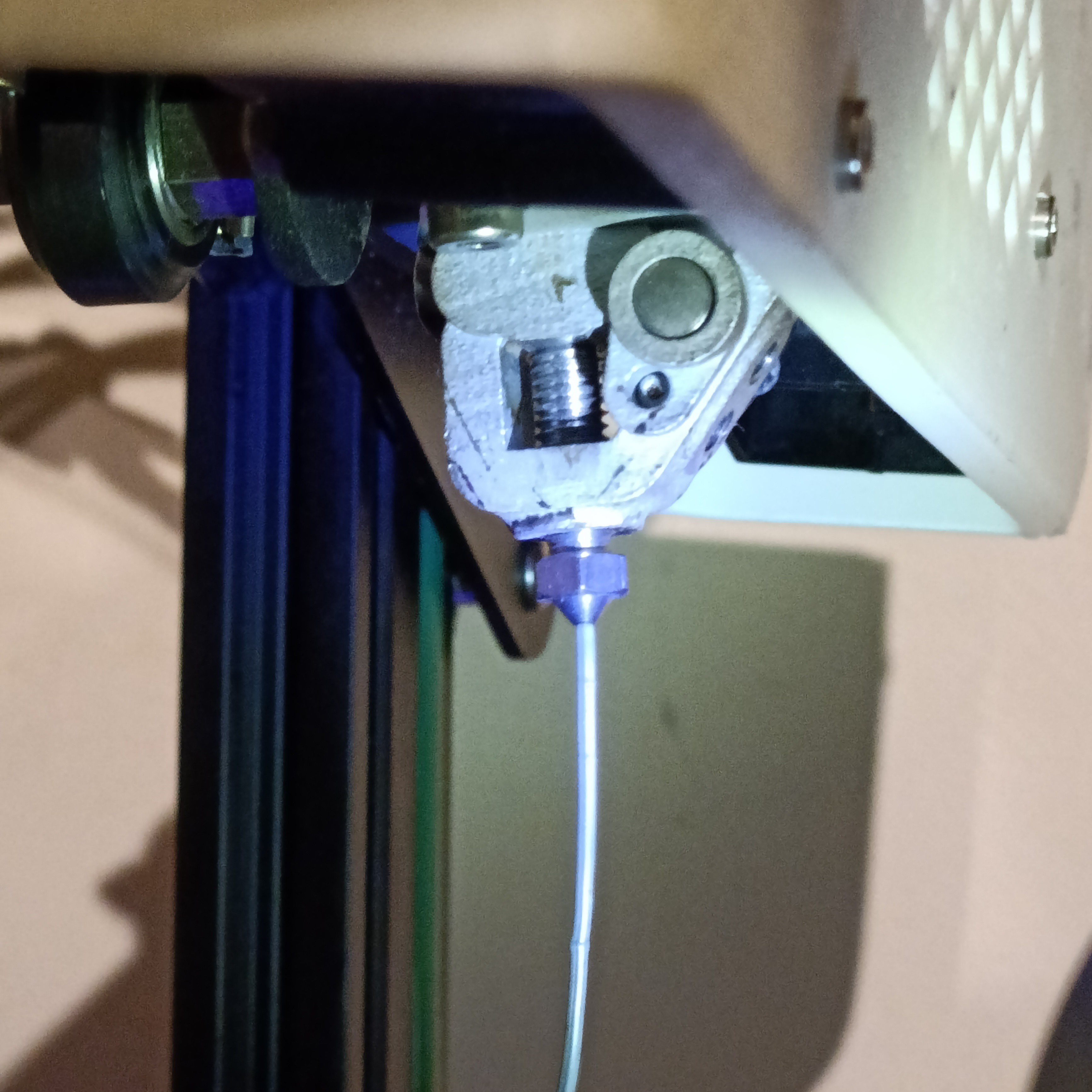
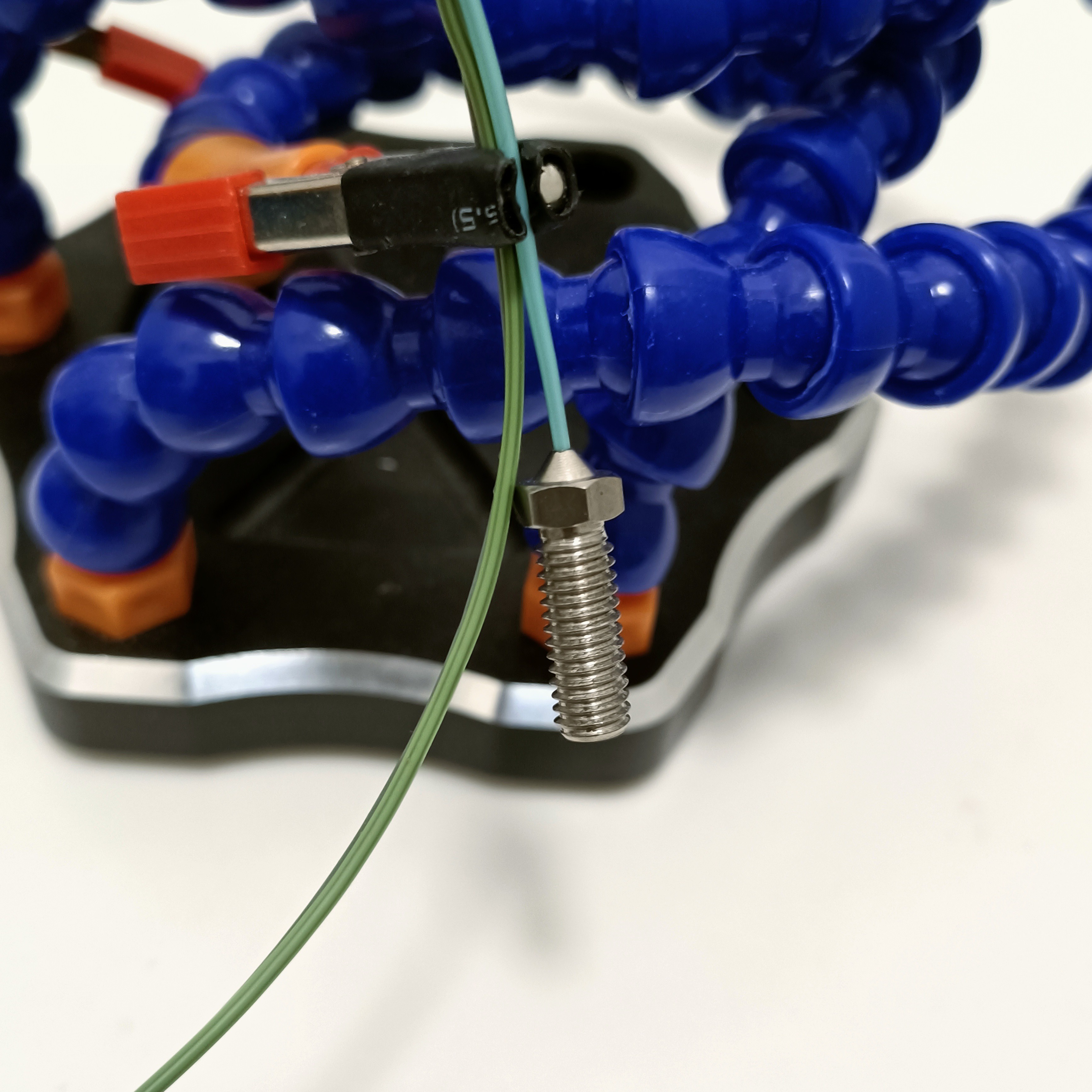
I bought the largest stainless steel volcano nozzle. The reason I didn't buy a standard brass one is because I intend to use this nozzle to "stamp" the R3 input/output holes instead of using abrasion.
I hoped to use the extrusion to push the material out of the nozzle but said extrusion swelled to 1.35mm so I didn't bother to try.
 The image below shows the extrusion cut at 4 sections, going further back in time from left to right:
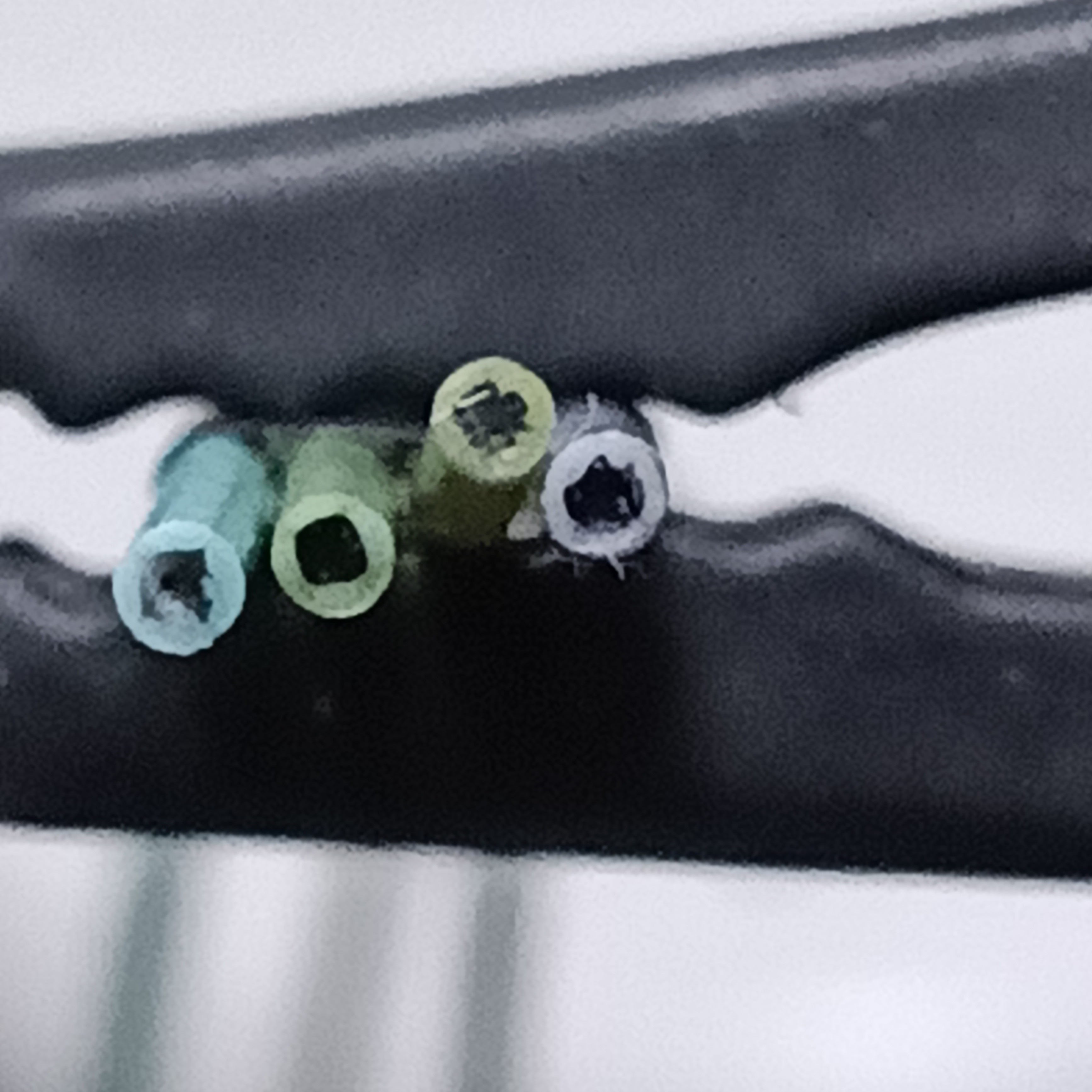
Now perhaps I should've extruded more than about 50cm of filament, but I was using the TFT24 and its "slow" speed indeed is slow, but it's "normal" speed seemed too fast for the R2 and it's inadequate meltzone. Out of the 4, the 2nd one to the left has the most consistent edge (hence the title).
I also cut one just before the nozzle to take a look:
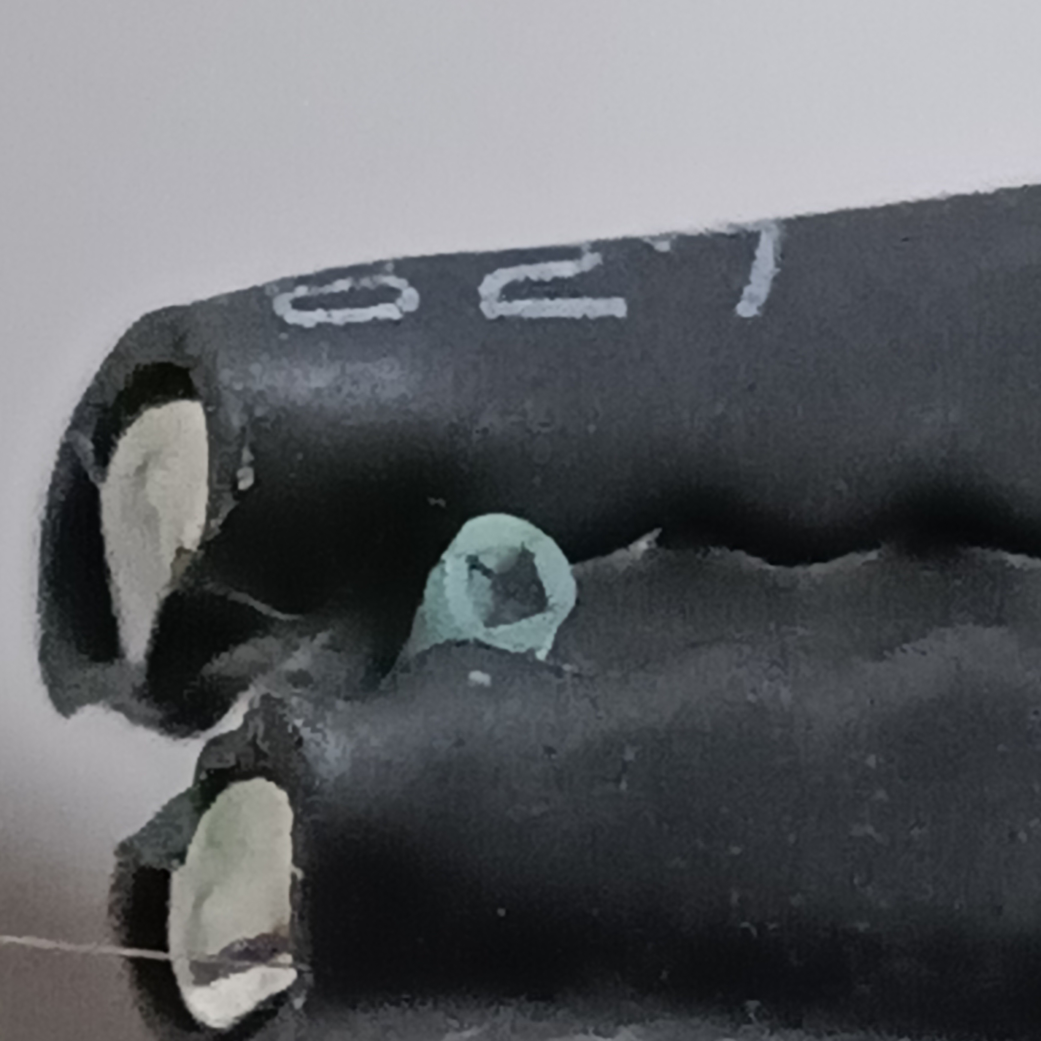 It kind of seems that the inner core is mid-transition.
R3 simulation
I also questioned if there was an even better way to see the ParaView results than using cutting planes or streams, and I did:
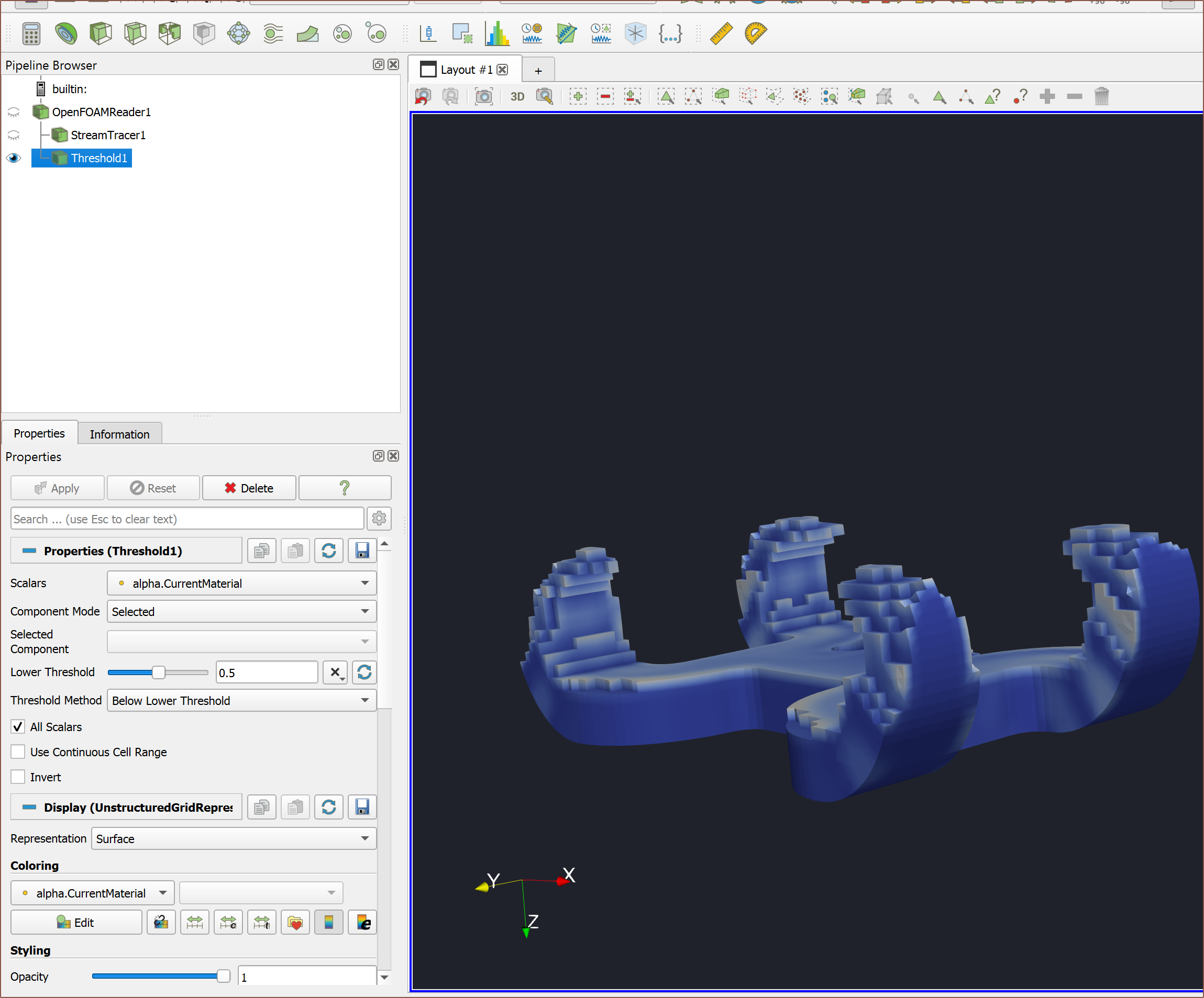
Using the threshold settings, I was able to get this cool visualisation that looks like a Minecraft speed build:

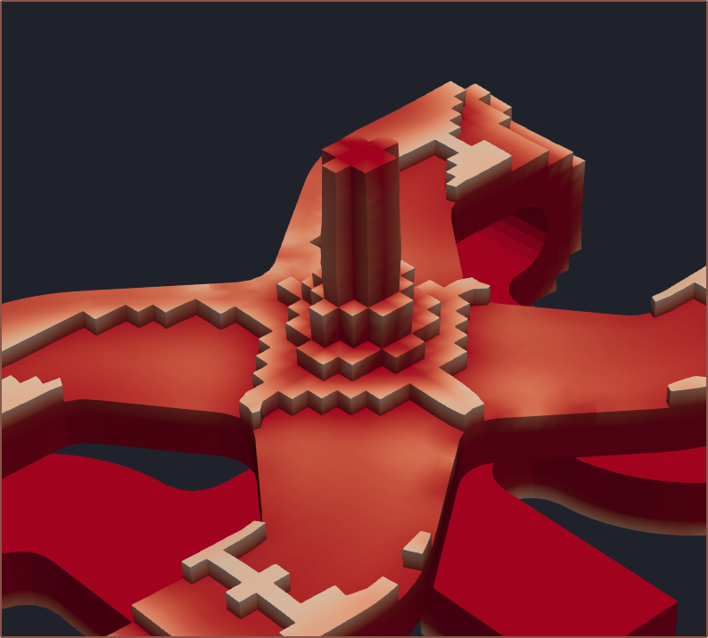
Since the input is split in primarily perpendicular directions, compared to R2 (below), it seems that the 4 paths arrive at approximately the same time, hopefully meaning that the output core would be more squircle.

Anyway, this is what the simulated core material looks like for R3:
[Nov 03]
I secured the 1.2mm nozzle to one of the aluminium plates and was trying to use the extrusion I left on it to push the material out of it. The PETG became much too floppy to succeed with that plan. However, the "task failed successfully" because the pushing and pulling caused the plastic at the nozzle input to flatten from the multicoloured cone it was initially, revealing the cross section:
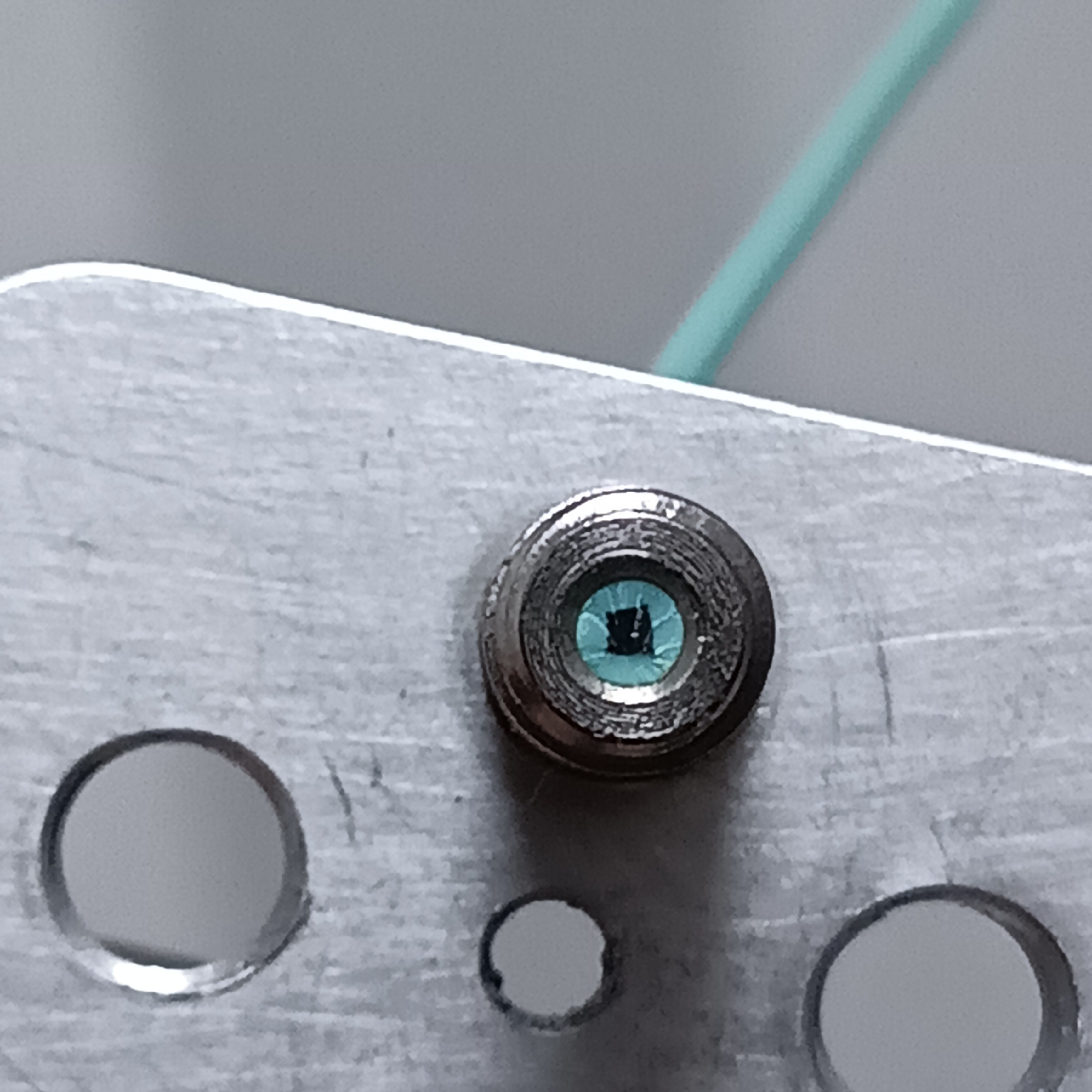
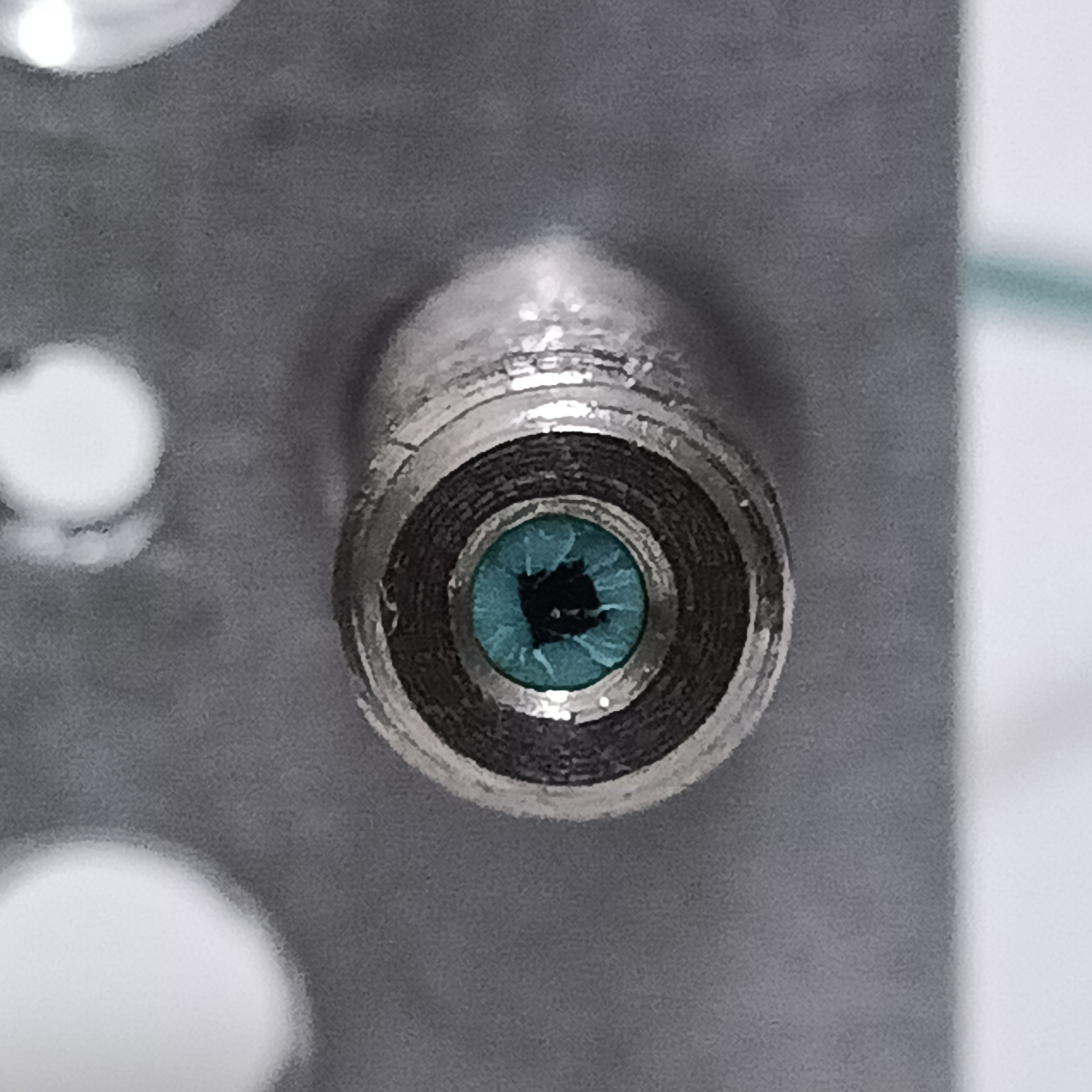
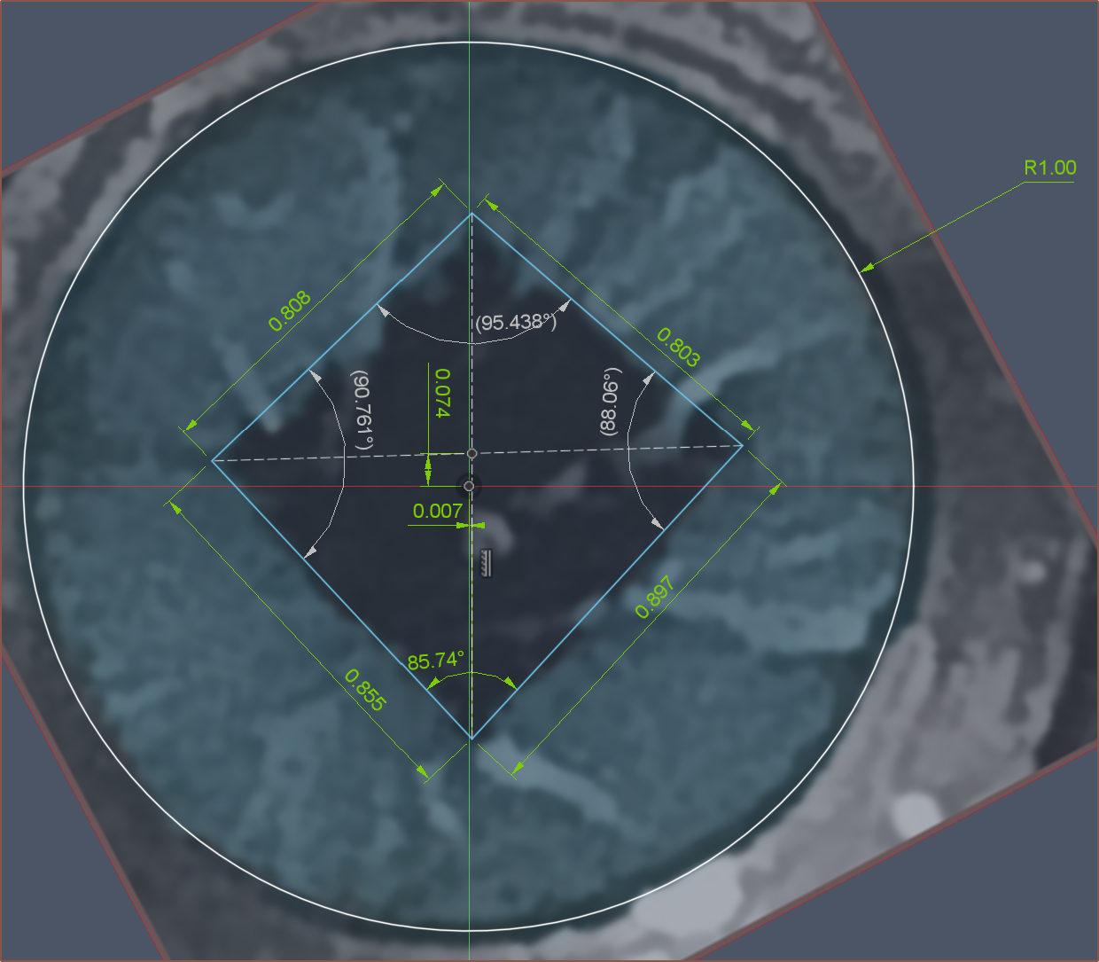
Black area: 0.705 mm^2
Cyan area: 2.436 mm^2
Ratio: 1 : 3.46
 kelvinA
Discussions
Become a Hackaday.io Member
Create an account to leave a comment. Already have an account? Log In.