 mrpendent
So....neopixels, huh? Those things are tiny. Very tiny. On the first first board, I got the diodes installed, then the sockets, then 3 neopixels. On #4--SHENANIGANS!!
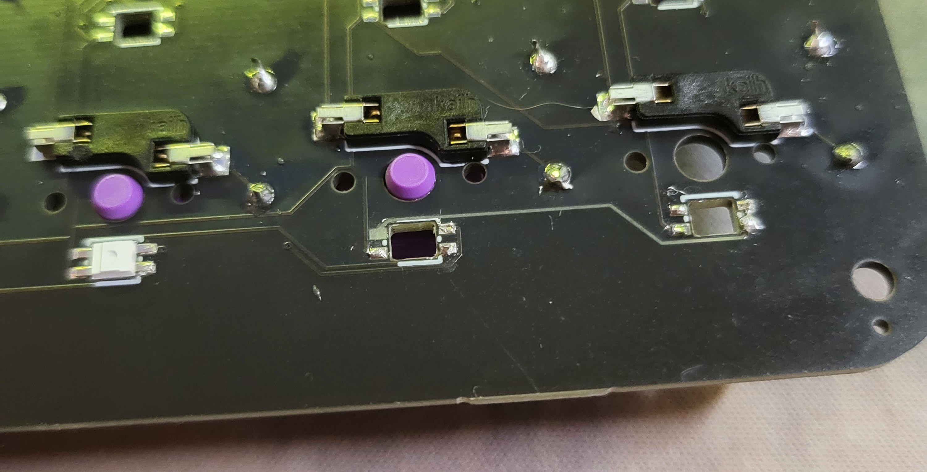
While trying to remove a messed up led, it actually peeled the solder pad AND the trace off the PCB. So I had to start again. The second time, I carefully put all the Neopixels on first (thanks to some advice from Ben Heck):
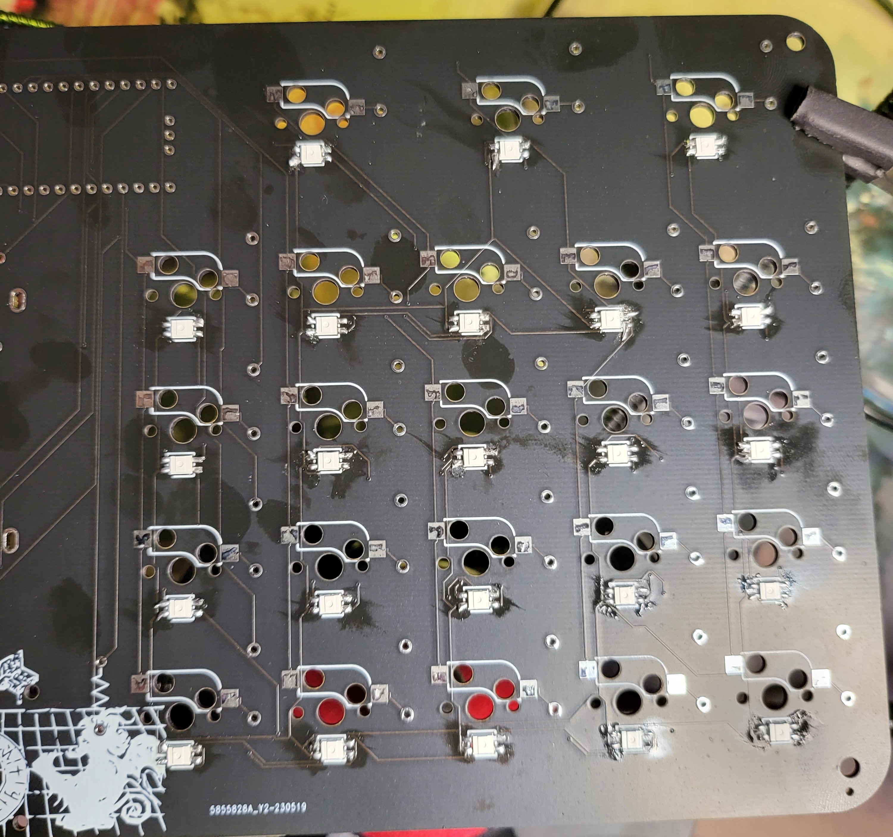
Then the sockets...
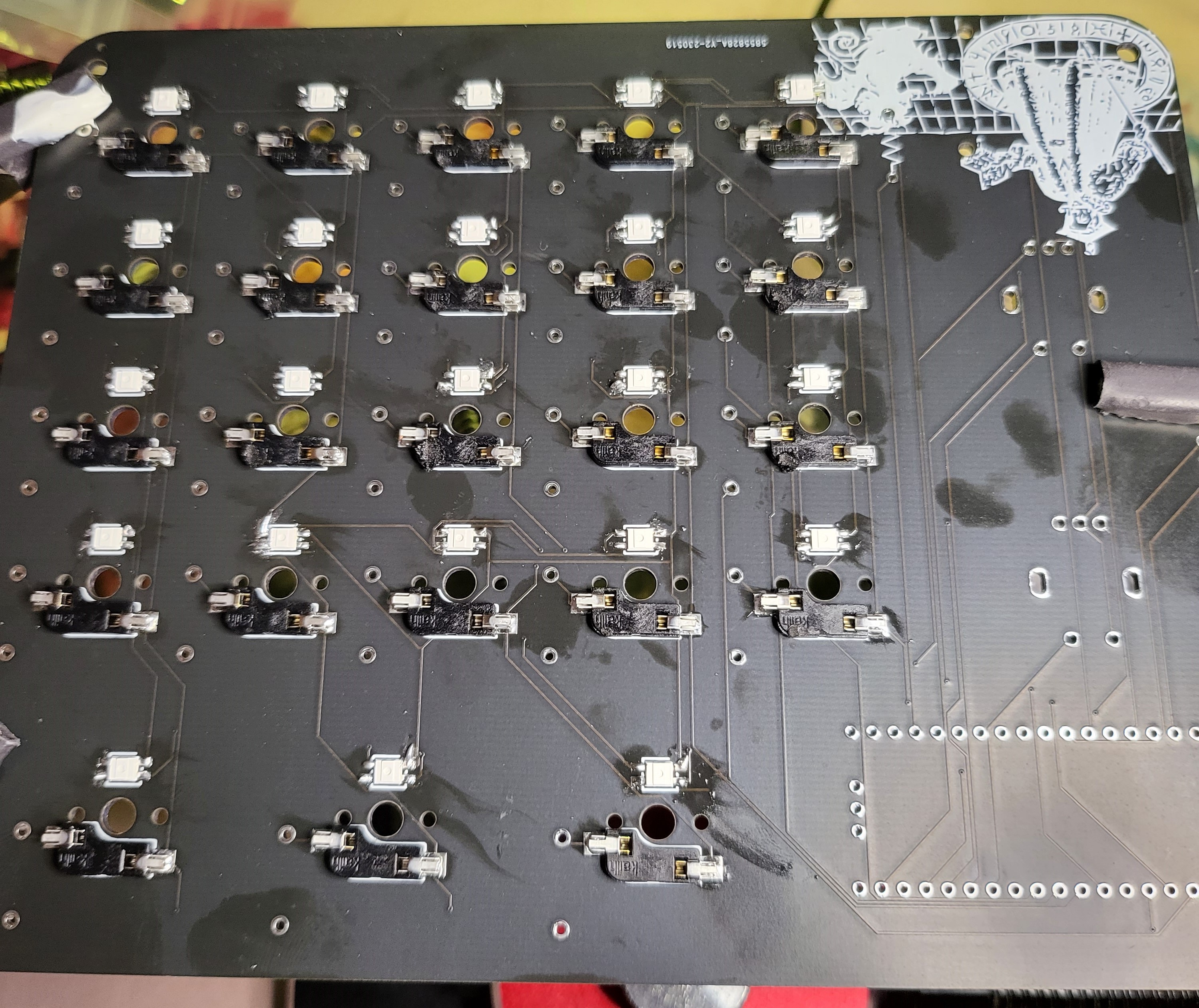
Then the diodes, encoders, and headers...
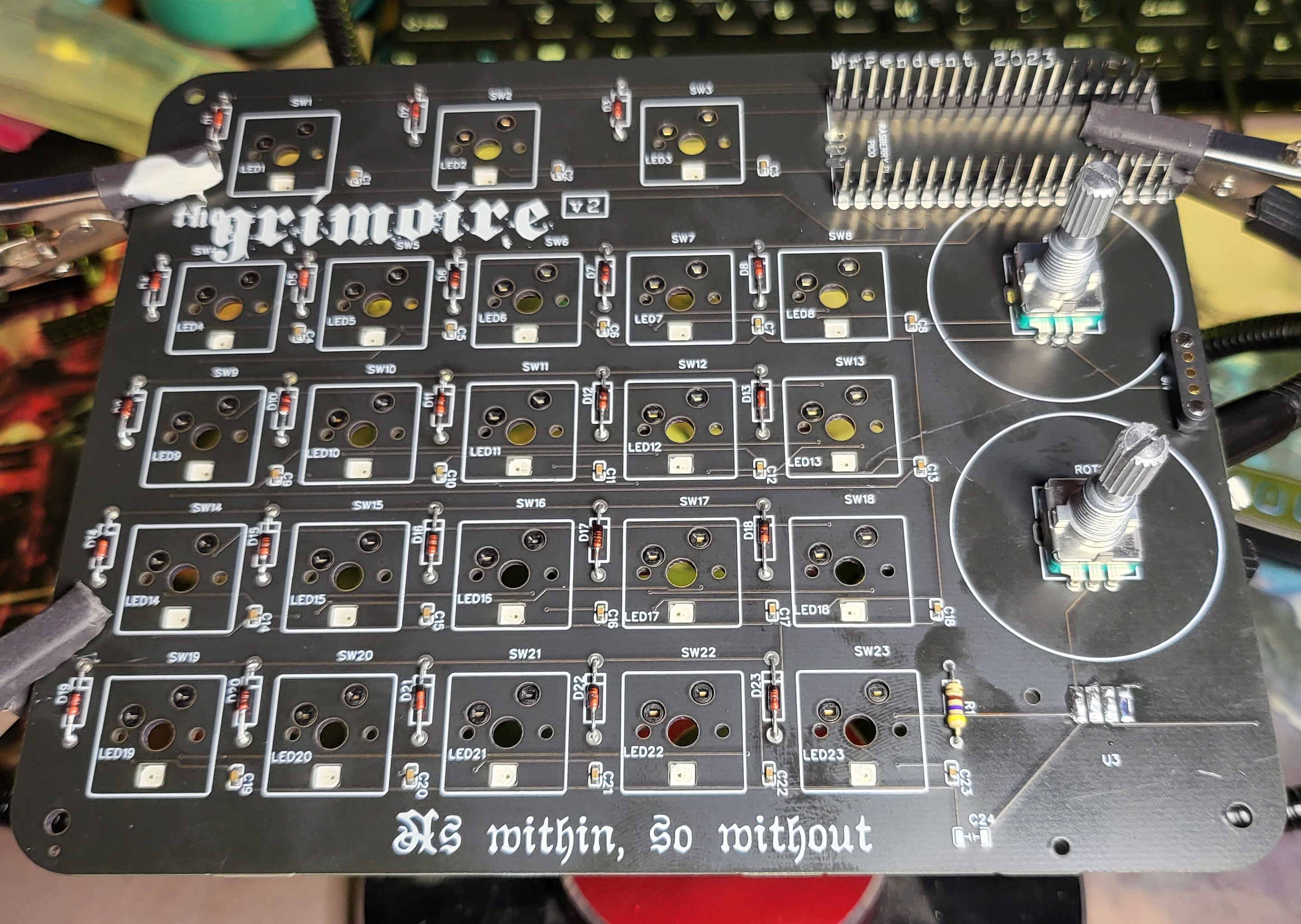
I had one issue--the joystick holes seem to be 2mm (I think? Maybe 1?) and I don't have screws that size to mount it. so I got the pads ready, but can't mount it yet. I'm a little worried about it still, but fortune favors the foolish. I love the look of the diodes--the translucent red with black ends remind me of some of the carpenter ants that I would see back in NM.
Next up:
- Get some screws for the joystick
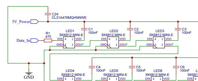
- Figure out what goes at C24 (the symbol is a capacitor. I think it was a 1000 mF cap to protect the LEDs)
- Install the SumoPi and give it a test
I'll be honest--I'm a bit scared of the last one. If it doesn't work after all this, I will be disappointed.
ps. Just a little image. Ignore this.
Discussions
Become a Hackaday.io Member
Create an account to leave a comment. Already have an account? Log In.