 mrpendent
Ok. I'm still getting confused here. Which means more research. I'm sure I can find the answer, but it's annoying that I have to keep looking.

I have been able to ascertain that the LEDs need the following:
- a single capacitor for the power. It is unlikely to cause a problem because this is drawing power from USB (5v), but a 1000 uF capacitor stops any chance of a surge eating my neopixels.
- A resistor on the data line before each pixel's DIN.
- A level-shifting chip, to translate the 3.3v from the Pico to the 5v logic expected by the neopixels
I tracked down a couple pre-made PCBs for keyboards by a company that definitely knows more about this than I do, and found these examples:
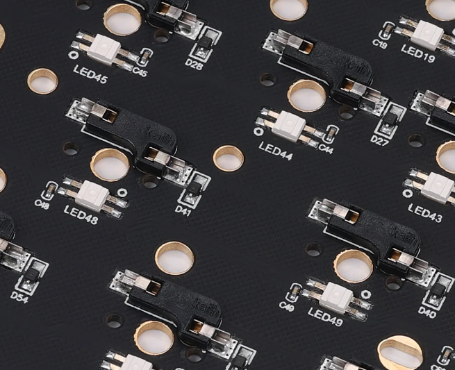
This is the back of the KBD Fans KBD75RGB. Clearly visible are the capacitors beside the LED, and the diodes next to the hotswap sockets. So this cements the need for a capacitor for each LED.
On the back of the KDB Fans DZ60RGB I can see the diodes for the keys, the LEDs, but the only capacitors seem to be at the bottom near that chip (which I assume is the level-shifting chip.

Also, down at the bottom we can see something labeled "Y1". A quick Google says that is a resonant filter, used to filter out stray signals (something called "debouncing"). So apparently I'll need that too, although I haven't seen that mentioned anywhere. No big deal, though I'm not sure where it needs to go--I assume on the DIN. That can just go on the list of stuff to figure out.
The bigger issue is how to wire in the logic shifting circuit (the 74AHCT125). The pins are as follows:
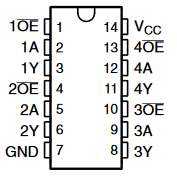
It is clear that we have 4 copies of the same thing, plus a ground and power line. Which means each "set" has the following: the OE (which Google tells me is Output Enabled), the A pin and the Y pin. It seems that the A is the input, which is combined with the OE, and then put out to the Y pin. Because I know this is supposed to stand between the Pico and the LEDs. I think that this would go to DIN, because that is where the high/low signals would be. I also think that I would only really need one "set" of pins. I suppose I could break the LEDs up into 4 rows, but I'm not sure there is a point.
I found this image to describe the wiring and it makes sense:
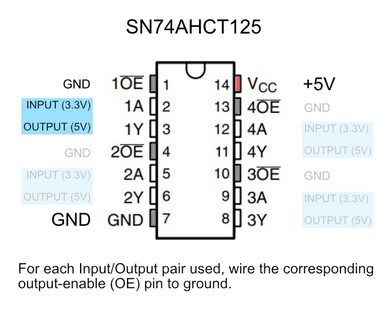
I think the bit I was missing was that +5v line. I think I need to to bring a power line straight from the USB......Which would be the VBUS on the Pico!

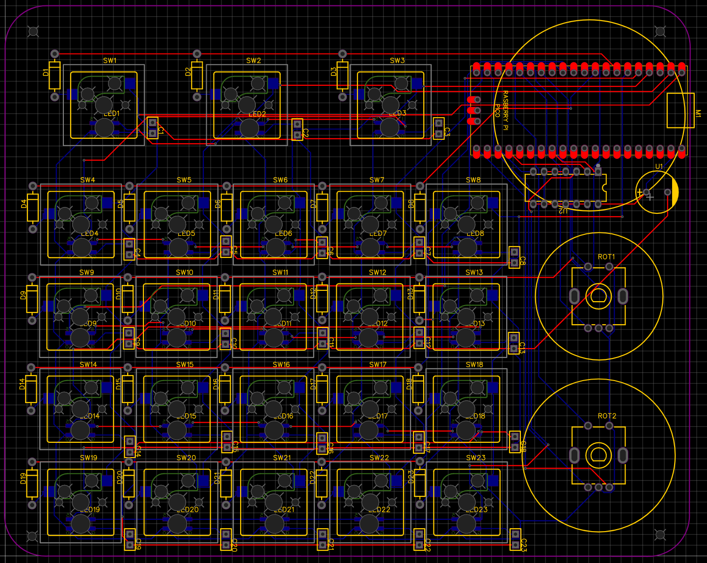
UPDATE: PCB has been updated. Now to let it simmer a bit.
Discussions
Become a Hackaday.io Member
Create an account to leave a comment. Already have an account? Log In.