 Steve Schnepp
Simulation works nicely, now let's try it out for real.
As Ken Yap nicely commented, there is a strong voltage drop in the bipolar NE555, typically 1.7V. The usual way is to leverage a CMOS version such as the LMC555, but as I'm aiming for very common components, I'll use only regular NE555.
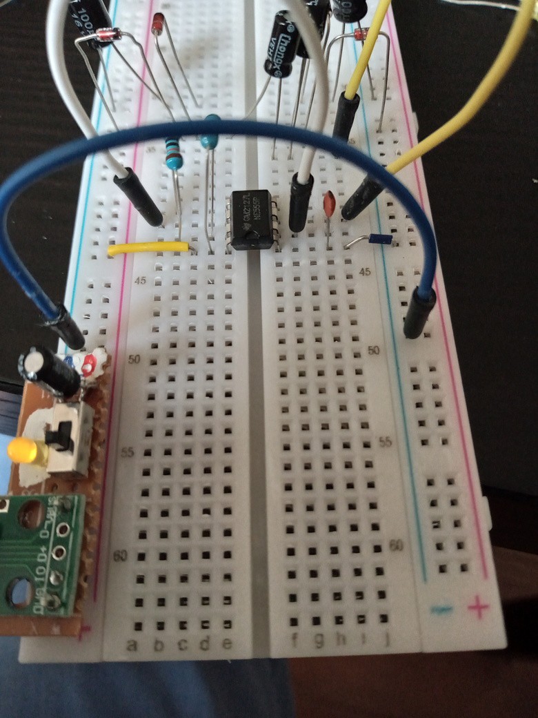
Building the charge pumps
The charge pumps are not hard to build. I'm using a simple breadboard, and a very simple DIY USB powering for 5V.
Testing the outputs
Now, it is time to test the 2 voltage outputs.
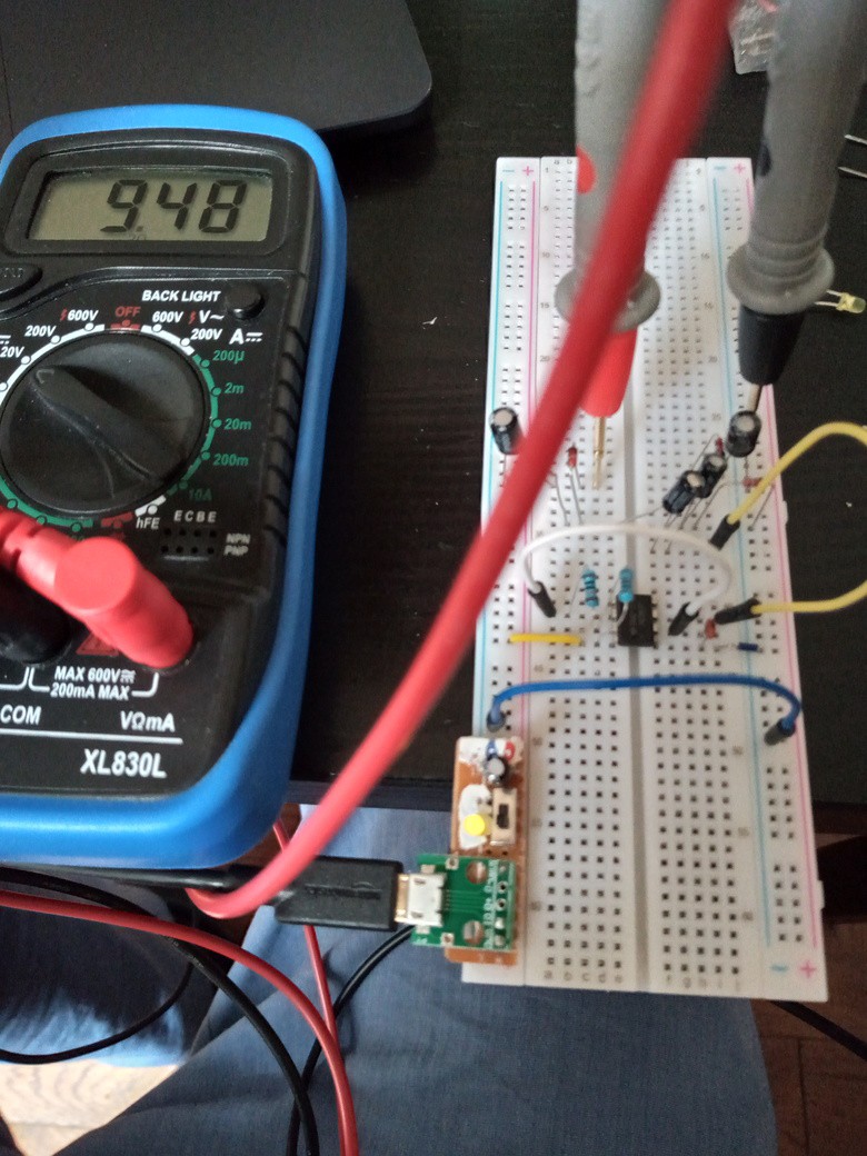
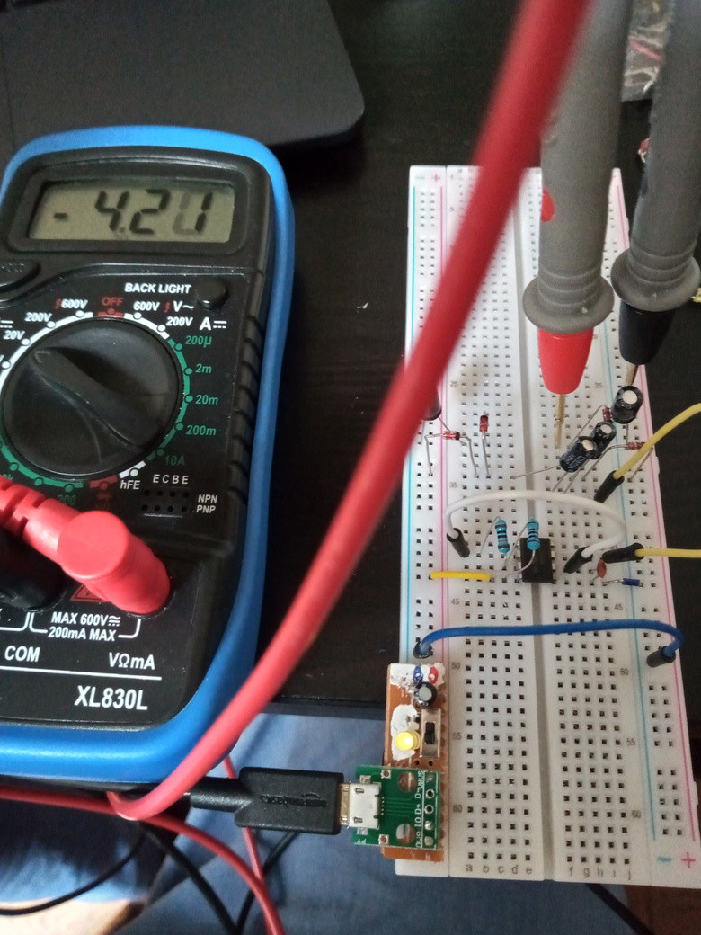
A very nice 9V and -4V.
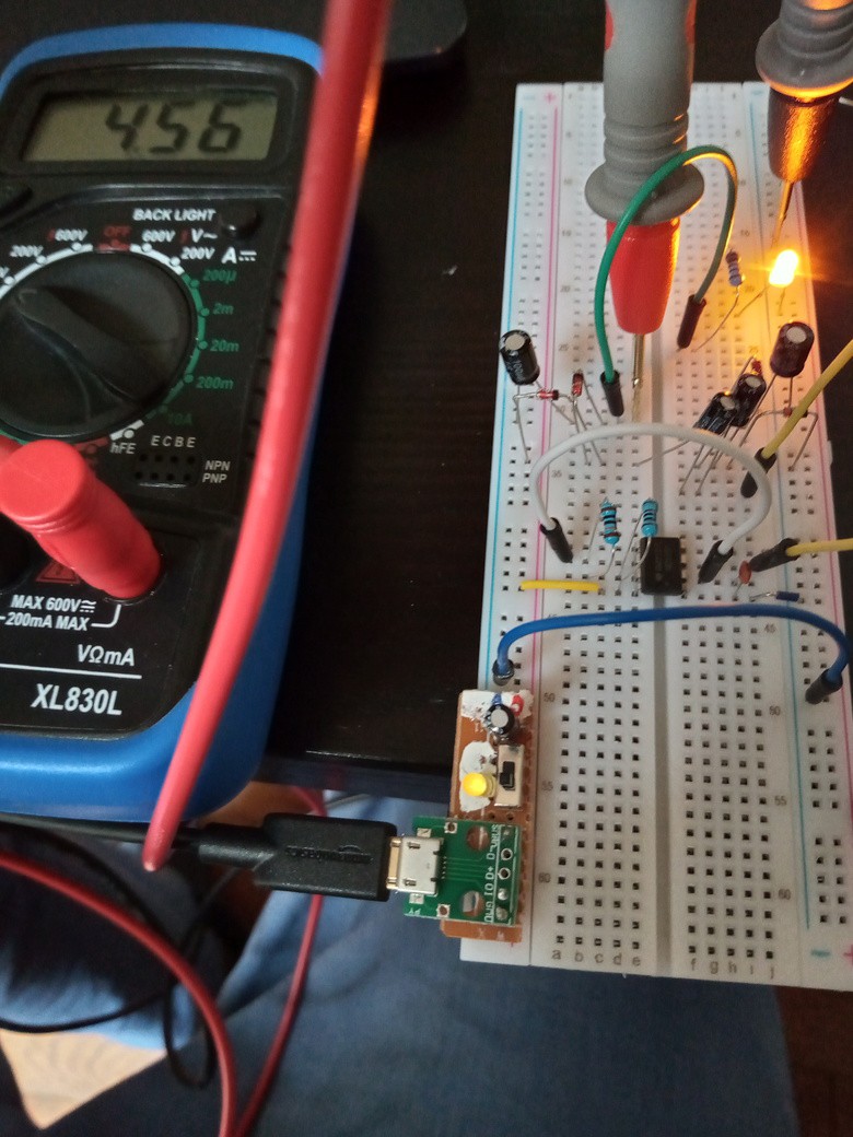
Issue is that it doesn't hold the voltage as nicely with some load. I tested with a yellow LED in series with a 1k resistors and it falls to 4.5v with a current of 2.4 mA (2.4V across a 1k resistor).
Anyway, let's try with the LM358 now.
Discussions
Become a Hackaday.io Member
Create an account to leave a comment. Already have an account? Log In.