 Subhajit
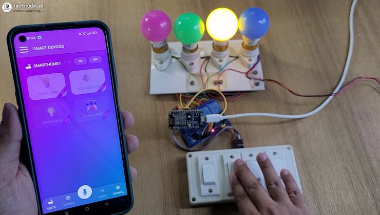
In this IoT project, I have shown how to make IoT-based Smart Home Automation using NodeMCU Cadio to control 4 home appliances from the Google Home, Amazon Alexa App, and Cadio.
 If the internet is not available, then you can control the home appliances from manual switches. During the article, I have shown all the steps to make this smart home system.
Tutorial Video on IoT Project using ESP8266 NodeMCU
This ESP8266 NodeMCU home automation system has the following features:
- Control appliances with the voice command using Google Assistant.
- Control appliances with the voice command using Alexa.
- Control appliances with the Cadio app.
- Control home appliances manually without internet.
- Monitor real-time feedback in the Cadio, Google Home, and Amazon Alexa App.
- Set Timer to control the devices automatically.
- Remember the previous state after the power cut (EEPROM).
- Can change the WiFi details through OTA.
- Don't have to write a single-line code. (No coding).
Required Components (Without PCB):

- ESP8266 NodeMCU.
- 4-channel 5V SPDT Relay Module.
- Switches or pushbuttons (4no)
Required Components (With PCB):

- Relays 5v (SPDT) (4 no)
- BC547 Transistors (4 no)
- PC817 Optocuplors (4 no)
- 510-ohm 0.25-watt Resistor (4 no) (R1 - R4)
- 1k 0.25-watt Resistors (5 no) (R5 - R9)
- LED 5-mm (5 no)
- 1N4007 Diodes (5 no) (D1 - D5)
- Push Buttons (4 no) or Switches
- Terminal Connectors
- 5V DC supply
Circuit Diagram of the ESP8266 IoT Project
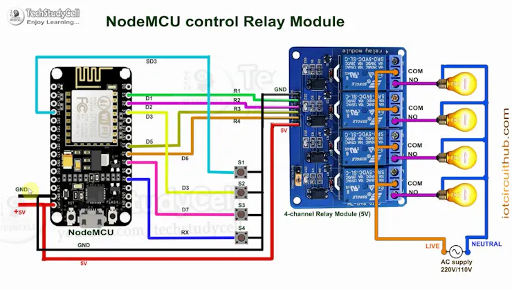
This is the complete circuit diagram for this home automation project. I have explained the circuit in the tutorial video.
The circuit is very simple, I have used the GPIO pins D1 (GPIO-5), D2 (GPIO-4), D5 (GPIO-14), and D6 (GPIO-12) to control the 4 relays.
And the GPIO pins SD3 (GPIO-10), D3 (GPIO-0), D7 (GPIO-13), and RX (GPIO-3) are connected with pushbuttons to control the 4 relays manually.
I have used the INPUT_PULLUP function in Arduino IDE instead of using the pull-up resistors.
I have used a 5V mobile charger to supply the smart relay module.
Install CADIO Firmware on ESP8266
To make this project, first, you must install the Cadio Firmware on ESP8266.

- The CADIO dynamic firmware for ESP8266 NodeMCU is available to download from the Downloads Center.

- ESP8266 CADIO firmware consists of a single binary file located at the address 0x0.
- SPI flash mode is DIO.
- SPI flash speed is 40MHz.
- Make sure that the DoNotChgBin checkbox is activated.
- You should erase the current flash before start flashing the firmware to avoid any issues.
- Now click on Start to install the Cadio Firmware.
Now reset the ESP8266 NodeMCU and wait for 30 seconds. The inbuilt LEDs will start blinking which indicates it is in config mode.
Configure the NodeMCU Using Cadio App

- Turn off mobile data and connect the "CADIO" hotspot created by the ESP8266.
- Open the Cadio app, and click on the 3-dash icon.
- Select Configuration.
- Select Switches Mode: "PRESS" for the push button. For latched switch select "NORMAL"
- Select Relay Mode: "ACTIVE LOW". For active HIGH relay select "ACTIVE HIGH".
Enter GPIO for Relays and WiFi Details

- Select the Switch wiring "PULLUP".
- Now enter the GPIO pins for the Config button, Indicator LEDs and Devices as shown in the picture. Then click on the tick icon (in the top right corner).
- Click on YES to export the info file.
- Select the WiFi Name and enter the WiFi Password. Also, enter a unique unit name and tap on the tick icon.
- Wait for some time the dashboard will appear automatically.
Now we have to connect the ESP8266 NodeMCU to the circuit. Although you can make the circuit without using any PCB, to make the circuit compact I have designed a PCB.
Design the PCB for This ESP8266 Project

To make the circuit compact and give it a professional look, I designed the PCB after testing all the features of the smart relay module.
You can download the PCB Gerber file of this home automation project from the following link and order it from JLCPCB.
Download PCB Gerber: GitHub Link
You can also use their SMT Service for your PCB order.
Why you should use JLC SMT Service?
On JLCPCB's one-stop online platform, customers enjoy low-cost & high-quality & fast SMT service at an $8.00 setup fee($0.0017 per joint).
$27 New User coupon & $24 SMT coupons every month.
Visit https://jlcpcb.com
JLCPCB SMT Parts Library 200k+ in-stock components (689 Basic components and 200k+ Extended components)
Parts Pre-Order service https://support.jlcpcb.com/article/164-what-is-jlcpcb-parts-pre-order-service
Build a Personal library Inventory, save parts for now or the future
Assembly will support 10M+ parts from Digikey, mouser.
Steps to Order the PCB Assembly from JLCPCB

1. Visit https://jlcpcb.comand Sign in / Sign up.

2. Click on the QUOTE NOW button.

3. Click on the "Add your Gerber file" button. Then browse and select the Gerber file you have downloaded.
4. Set the required parameter like Quantity, PCB masking colour, etc.

5. Select the Assemble side and SMT Quantity.

6. Now upload the BOM and PickAndPlace files.

7. Now confirm all the components which you want to be soldered by SMT services.
8. Click on the SAVE TO CART button.
Select Shipping Address and Payment Mode

6. Type the Shipping Address.
7. Select the Shipping Method suitable for you.
8. Submit the order and proceed with the payment.
You can also track your order from the JLCPCB

My PCBs took 3 days to manufacture and arrived within a week using the DHL delivery option.
PCBs were well-packed and the quality was really good at this affordable price.
Solder All the Components on PCB

After that, I soldered all the components as per the circuit diagram.
Then connect the NodeMCU board with the PCB.
Now turn on the 5V DC supply. If the NodeMCU is connected to WiFi, the in-built blue LED will turn ON.
Change the Device Name in CADIO App

- You have to long-press the related device button.
- Now tap on "Settings" to open the setting page.
- Give a Device name and select the Device icon. Then tap on the tick icon to exit. In a similar way change the device name for all the devices.
- In this way, you can change all the device names as per requirement.
Control Relays With Cadio App

If the NodeMCU ESP8266 is connected to WiFi, you can control the home appliances from Cadio App.
You can also monitor the real-time feedback from anywhere in the world.
Connect CADIO With Google Home
- Open the Google Home app and create a Home.
- Then click on "+" and select "Set up device", the " works with Google".
- Now search for CADIO, and log in to your CADIO account.
- All the devices from CADIO will be added to Google Home.
Now you can also control the appliances with voice commands using Google Assistant.
Connect CADIO With Amazon Alexa

Linking CADIO account with Amazon Alexa
- Open the Amazon Alexa app then click on YOUR SMART HOME SKILLS.
- Click on ENABLE SMART HOME SKILLS.
- Type CADIO in the Search bar, then click on CADIO.
- Click on ENABLE TO USE to enable CADIO skill.
- Now Log in using your CADIO account.
- Your CADIO account is now linked with Amazon Alexa.
- You can now control your smart devices from the Amazon Alexa app and supported devices.
Connect the Appliances With the PCB

Now connect the appliances with PCB as per the circuit diagram. Please take proper safety precautions while working with high voltage.
Connect the 5-volt DC supply with the PCB. (I have used my old mobile charger)
Now your ESP8266 home automation system is ready.
I hope you have liked this Cadio home automation project. I have shared all the required information for this project.
I would really appreciate it if you share your valuable feedback. Also if you have any queries please write in the comment section.
Thank you & Happy Learning.