Close
0%
0%

Arduino-Programmable Cortex M4F Development Boards

Program an STM32L4 Cortex M4F with the Arduino IDE via USB

Similar projects worth following
Butterfly and Ladybug STM32L4 Development Boards

Simple design, easy to program, high-performance and ultra-low-power embedded solutions

Technical Specifications

Microcontroller: STM32L4 ARM Cortex M4F
Clock speed: 1, 2, 4, 8, 16, 24, 32, 48, 64, 80 MHz
Operating voltage: 3.3V
I/O pin limits: most pins 5.0 V tolerant, 20 mA
Digital I/O pins: 22, with 11 PWM (Butterfly), 13, with 8 PWM (Ladybug)
Analog input pins: 6 (Butterfly), 5 (Ladybug), 12-bit ADC channels
Analog output pins: 2 12-bit DAC
RTC: 1 ppm accuracy
Flash memory: 256 KB SRAM: 64 KB
Voltage regulator: 3.3-5.5V input / 3.3V, 150 mA output
Dimensions: 1.4 x 0.7" (Butterfly), 1.1 x 0.6" (Ladybug)

These are for sale now at Tindie!

Where we started

Ever since I first learned how to use my beloved 8 MHz Arduino Pro Mini with the Arduino IDE I have pined to move up to the more powerful STM32F4 with its faster CPU clock, floating point engine, and rich peripherals. I bought STM32F4 Nucleo and Development boards and used mbed to program them but this was a very frustrating experience. mbed is sufficiently different from the simplicity of Arduino that I literally had to completely rewrite my sketches just to get them to compile. I don't know how many times I tried to use adult tool chains like Keil and gcc/eclipse to program these powerful MCUs but I never even got past the installation process getting stuck somewhere in the complicated series of steps to download and install various parts of the tool chain. I took several ST-sponsored training classes to learn how to use ST-Link and the STCubeMX system with the Keil and IAR tool chains to blink leds and read sensors. But when I tried to use the STM32 development boards at home I could never get them to work. Frustration maximized, I turned to the Teensy 3.1 for my projects and rejoiced in the ease of Arduino programming via the USB and forgot about the STM32 for a while.

When ST released the first STM32L4 MCUs my interest was rekindled. Here was offered the performance of the STM32F4 with a floating point engine plus the low power consumption demanded by many of my battery-powered wearable and remote logging projects. I immediately designed a development board for the STM32L476 and tried to program it using ST-Link and STCubeMX after taking yet another ST class on how to program the STM32L4. I couldn't make it work, but fortunately for me Thomas Roell noticed my design on the shared space at OSH Park and asked to collaborate on improving it. There and then our deal was struck: I would design and build the hardware, he would design and build an Arduino core and we would both test and use what has become one of the highest performance MCUs available to the Arduino community.

We started on Tindie with Dragonfly, an STM32L476 using the 10 mm x 10 mm LQFP64 package, with 16 MByte QSPI flash on board, a supercap for RTC battery backup, an rgb led, 16 MHz and 32.768 kHz crystals, and all GPIOs exposed to the user including the SWD port for those who might want to use a ST-Link to program the board the old-fashioned way. What a delight to have access to an 80 MHz MCU with FPU including five serial ports, three SPI ports (or two plus an I2S port), three I2C ports, one CAN port, thirteen PWM-compatible pins, and two separate DACs, all programmable through the USB using an Arduino IDE and standard Arduino APIs. It was like having a Teensy 3.1 on steroids!

Where we are now

We realized that not everybody needed the extra hardware and peripherals that were included with Dragonfly. So now we would like to extend the Dragonfly family to make use of the latest STM32L4 MCUs that come in smaller and more cost-friendly packages; Butterfly with the STM32L433 and Ladybug using the STM32L432.

Butterfly (0.7" x 1.4") and Ladybug (0.6" x 1.1") are small, low-cost development boards with simple, open-source designs that will allow just about anyone to make use of the STM32L4 in their own custom applications. They rely on a single, inexpensive 32.768 kHz crystal oscillator and don't require the ST-Link built in to the STM32 Nucleo boards. Applications can be developed using the Butterfly and Ladybug development boards which provide access to all GPIOs and peripherals of the STM32L4. When the application has been sufficiently proved out, application-specific hardware can be designed using the STM32L43X development board as a design template. The 7 mm x 7 mm QFN48 and 5 mm x 5 mm QFN32 packages of the STM32L433 (Butterfly) and STM32L432 (Ladybug), respectively, are space-efficient, low-cost but still powerful solutions to embedded computational and sensor management problems. Better still,...

Read more »

  • Low-Power Environmental Sensor

    Kris Winer01/15/2017 at 17:59 0 comments

    It has been a long standing goal of mine to create an environmental sensor/data logger that could run on a small battery for long enough to collect data from a remote location unattended for a few weeks for later analysis.

    I tried first using the Teensy 3.1 with this add-on, but the best I could do was about 24 hours or so on a 750 mAH LiPo due to the ~30 mA current draw of the MK20 MCU. Now to be fair, I was never quite able to get the SNOOZE library to work the way I wanted and it is possible one could do better today. But the low power modes available for the Teensy are limited.

    I then tried the ESP8266/85, Espressif's wonderchip with the embedded wifi. Now, wifi has a reputation as a power hog and it is true in default mode, but I figured out how to invoke the light sleep mode on the ESP8266/85 and, with this device, got the average power usage down to ~10 mA or so. With the device broadcasting pressure, humidity, temperature, and light level every 30 seconds I was able to get out to the same 24 hour duration with a 300 mAH battery. Progress but still not what I wanted.

    Now the STM32L4 is specifically designed for low power applications, and I am in the middle of my first really successful experiment. I designed an add-on board with a BME280 pressure, temperature, humidity sensor and a VEML6040 red, green, blue, white ambient light sensor to mount on the smallest STM32L4 development board, Ladybug. I am using a few tricks to drop the power usage as low as I can while preserving the state information (not requiring reinitialization of all sensors and registers).

    One is I am taking advantage of the STM32.stop(timeout) command at the end of the main loop to suspend the MCU in between data read, processing, and display for five seconds. Of course, the longer the timeout, the lower will be the average current. But for slowly varying data like pressure temperature, humidity and light level, a five second reporting interval seems quite reasonable to me.

    The other is I am taking advantage of the enable/disable functionality of the VEML6040, since it is the big power user of the two sensors at an average current of 200 uA (this is large in the world of low power!). At the start of the main loop I enable the VEML6040 sensor, wait for a conversion time of 160 msec, read the data, then disable the sensor. This drops the average power usage to ~200 *(200/5000) ~ 8 uA, still higher than the ~4 uA of the BME280 sensor running full blast but a lot lower than 200 uA.

    The other nice thing about the STM32L4 is that the embedded RTC allows a time and date stamp for the data, and the RTC can be calibrated for better than 1 ppm accuracy. In my experiments with the RTC uncalibrated it is gaining about one second per day.

    You can see the full Arduino sketch with these methods here.

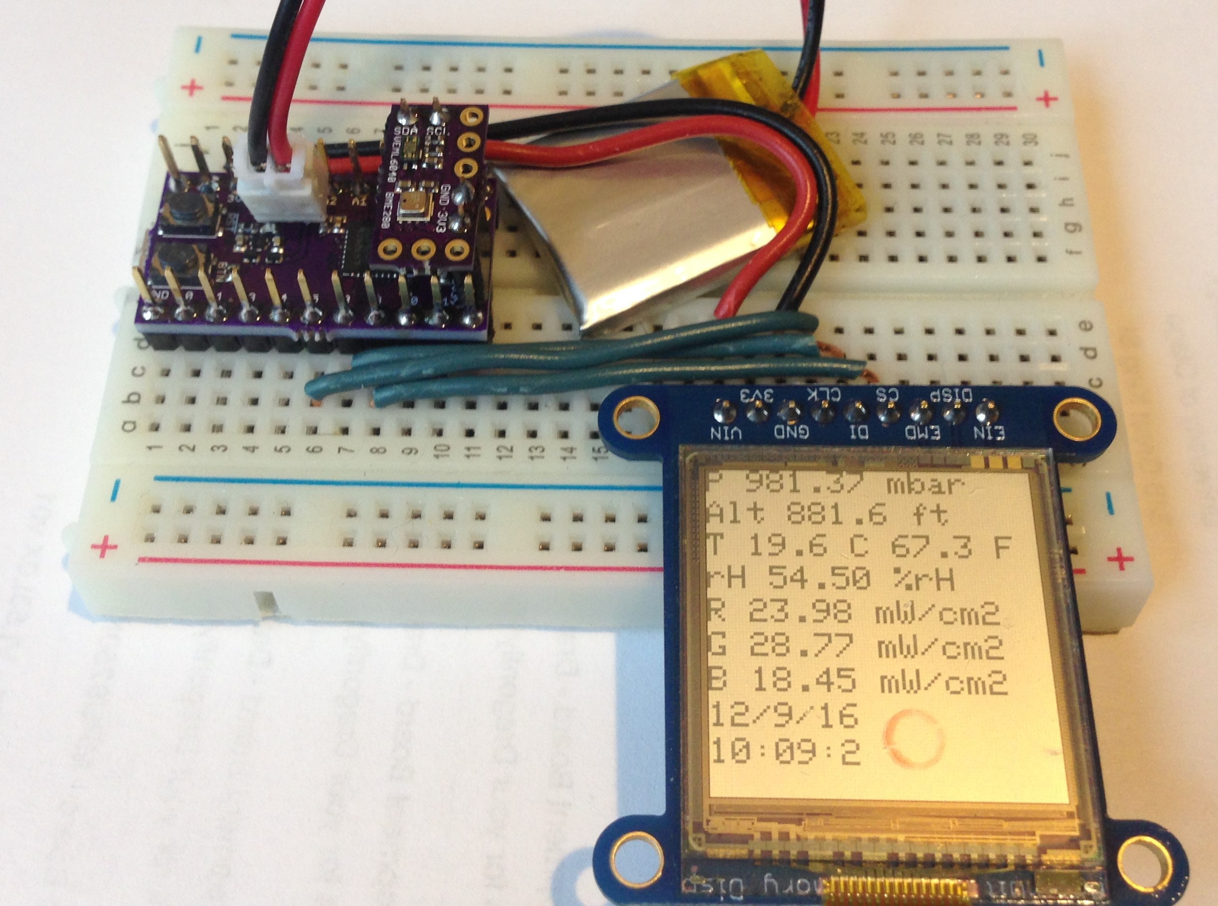
    This is what the environmental sensor experiment looks like:

    You can see the add-on board with the sensors mounted on female headers on top of the Ladybug, itself stuck in a small breadboard with a Sharp memory display to show the data, all powered by a 150 mAH LiPo battery.

    I last restarted the experiment after including the enable/disable trick for the VEML6040 sensor on December 27, 2016 at 11:33 AM. As of today January 15, 2017 at ~10 AM it has been running for 18 days and 22.5 hours for an average current usage of ~330 uA. At this rate, using a 350 mAH LiPo battery instead, I should be able to remotely collect data and store it on a low-power SPI NOR flash memory for > 1000 hours or 44 days. Of course, I could just add a bigger battery but I calculated that the 24 bytes I need to account for all of the information provided by the sensors every five seconds would fill up a 16 MByte SPI flash memory in about 900 hours. So this device looks like my first practical environmental data logger which allows long-term data collection in a very small package at a very economical cost.

    Update #1: Still going strong on January 17 at 8:00 PM for a total of 21 days 8.5 hours (512.5 hours)...

    Read more »

  • Touch pad to demonstrate STM32L4 touch sense controller

    Kris Winer01/10/2017 at 21:50 0 comments

    Our kickstarter did not meet its goal but we now have 100 or so people who know about this project and want these boards. That is a success!

    We created a store on Tindie where we will offer the Ladybug and Butterfly Development Boards as well as useful accessories as we design and assemble them.

    The latest accessory is a touch pad to make use of the touch sense controller embedded in the STM32L4. There are three useable touch pins on Ladybug, six on Butterfly and twelve on Dragonfly in groups of three. The touch pad has two sets of three finger pads connected to edge pins including the required reference connector. The way the touch sense controller works is the reference capacitor is charged and compared to the sensing capacitor to determine if and when a pad was touched.

    Here is a link to an ST presentation describing the touch sense controller.


    We want to have sufficient hardware peripherals available (the touch pad will be listed at Tindie when we have tested it) to allow users to make full use of the STM32L4 using the Arduino IDE. Even though the expectation is that most users will design custom hardware using the development boards and their peripherals as templates, it is always better to have a working example first before the designs are diverted to custom applications.

View all 2 project logs

Enjoy this project?

Share

Discussions

Kris Winer wrote 02/14/2017 at 04:48 point

I have used the fft analyzer in the ArduinoSound library and it works fine, but I am a bit disappointed in the broadening of the normal modes it produces. This might be due to improper configuration on my part. But the worst problem is that the size of the code using this library is enormous because of the giant lookup tables they use or something, not sure. If you get the fft to work on your Butterfly and the performance and code size are reasonable, I would sure like to make use of it for my self. So when the time comes I hope you will share it wth me!

We are in the process of making ESP8285 wifi add ons available for Ladybug and Butterfly (next week or so) and we are designing a BLE add-on also (nRF52) that can be configured completely from the Arduino sketch on the STM32L43X side. This will be available in a month or two. Lastly we will also add a LoRa radio add-on and/or a LoRa development board using the Murata STM32L0+LoRa radio module. This latter is still in the design stage but we want to have a cheap and convenient wifi, BLE, and LoRa radio solution available for these dev boards.

  Are you sure? yes | no

NickWaterton wrote 02/14/2017 at 04:36 point

This looks just like what I'm looking for! I've been trying to build an audio frequency analyzer, but battery powered, with a battery life of 6 months or so. Data to be sent by (sort of) BLE. I have the super low powered BLE module, (which publishes via mqtt!), but it uses an event driven RTOS, so I can't perform real time measurements - not fast enough for audio anyway. Oddly enough it's a low power cortex M4, but with low powered 2.4 GHz radio built in (Nordic).

The idea was that the sensor would be asleep most of the time, only waking up when sound is detected (over a threshold), then the frequencies are analysed over a few 100ms, and an event triggered if a pattern match is found.

I finally bit the bullet and added a second MCU (an old teensy 3.2 I had lying around). I can do the fft with a MEMS microphone fine with the teensy, but the power consumption!

I have a butterfly and a 43434 MEMS microphone on order. Im hoping to do fft on it the same way as teensey. We'll see when it arrives!

Keep up the good work

  Are you sure? yes | no

Similar Projects

Does this project spark your interest?

Become a member to follow this project and never miss any updates