 Florian Wilhelm Dirnberger
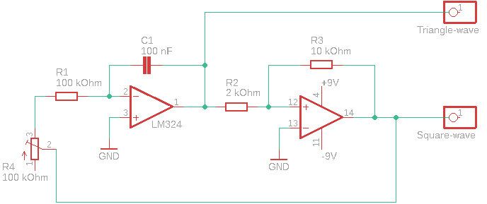
1. Schematic
As with any oscillator, no input is needed. It swings by itself.
For example: decreasing capacitor C1 to a 10 nF value would lead to a tenfold increase of the frequency.
2. Functional description
The first OP stage is an integrator (negative feedback loop), the second a non-inverting Schmitt trigger (positive feedback loop).
The wave is triangle shaped on the integrator output (IC pin 1) because the capacitor is forced to charge linearly: the current through resistor R1 is constant and the input of the OP Amp draws (virtually) no current.
The gradient x (V/ms) is calculated by the following formula (U_s would be 9V here):
R2 and R3 determine the voltage thresholds (therefore the oscillator frequency) of the Schmitt trigger.
No reset switch for the integrator is needed, for it is part of a more extensive device (i.e. oscillator).
3. Power supply
A symmetrical power supply is needed, in this arrangement realized thru an additional OP arrangement consisting of an UA741.
4. Application
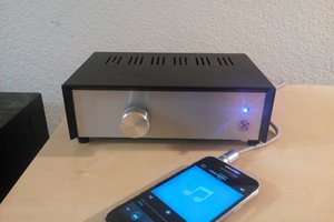
The oscillator could be part of a sound generator/synthesizer.
A triangle signal generates a very distinctive, not too unpleasant sound - triangle signals consists solely of odd harmonics: 1st, 3rd, 5th, etc..
 _electroidiot
 Szoftveres
 Ellie T