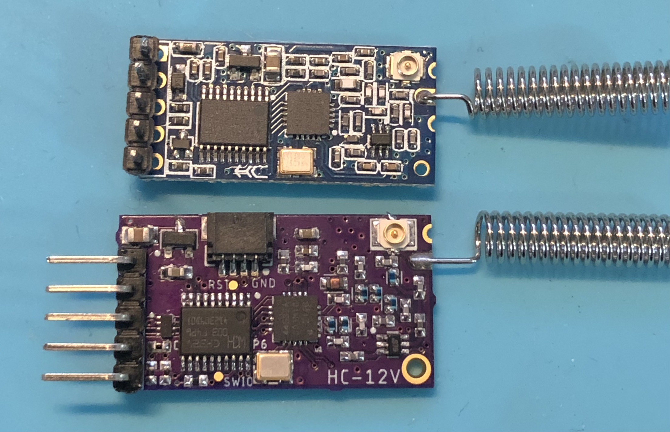
For some reason, I thought that I had all the required passives in my horde of components - alas no. I ordered it all and finally got round to assembling the boards.
As I didn't order a stencil, I had to manually apply solder paste to the pads. I used whatever I had on hand. (Note to self - get new paste!). The 0402 components were ok, but the RF IC and the level converter IC are really tiny, so I had to use the "blob on and wick off" technique. I hand placed the components, then reflowed on a hot plate. A couple of the 0402s wanted to tombstone.
After getting everything looking OK, I went to clean the pcb in 100% isopropyl......but I realised that the paste I had used had No-Clean flux - leaving a white residue everywhere.......
After a go with some proper PCB cleaner, they started looking reasonable.

Time to program something.
One issue I realised very quickly was that the 0.8mm test pad I was intending to use for programming is way too small. After I soldered a wire to it, it just ripped up off the board! I taped the wire to the back of the PCB for support and soldered it direct to the SWIO Pin (Pin 18).
I connected the WCH-LinkE programmer to VCC, GND, SWIO and RX. After creating a new blank project in MounRiver Studio IDE, it still has some basic USART loopback code in it. This would be a good test to see if everything is working. Next problem - the project wouldn't download as the firmware for the WCH-LinkE was not up to date. I tried clicking "Yes" to upgrade the firmware, but it failed. Then it didn't recognise the debugger :-( .
Some googling on the steps to manually update the firmware revealed that I'd need to press the "IAP" button, then try to upload again. The button is inside the strongly stuck together clear case of the programmer. No access to the buttons! Rather than break the case, I drilled a 2mm hole in the plastic, then used a paperclip to press the button. This was supposed to turn on a blue LED, but that wasn't working for me. The update wouldn't get triggered as the IDE kept saying that no programmer was connected. In the end, I ran the WCH-LinkUtility, and ran the "Target > Connect WCH-Link" option, which DID prompt to upload new firmware. Success! The WCH-LinkE could detect the connected CH32V003.
I downloaded the program to the device. Programming successful!
But the USART didn't seem to be responding........
I checked all my soldering and that seemed to be ok. Next step is to check the schematic......
Looks like didn't read the datasheet of the USART level shifter IC - TXU0202DTTR . I had wired the incoming TX pin straight to the RX pin. I had picked this chip as it offered the full 1.1v - 5.5v on each side of the serial bus. This would allow connection to most external microcontrollers, plus allow the chip to work at a range of voltages if required. In hindsight, the small SON package I chose is a pain to solder... I should have stuck with the VSSOP with external pins.
To get these prototypes to work, I just needed to remove the level shifter and solder a really fine wire across the pads to bridge the incoming pins to the MCU pins. The tiny pads made it hard to get enough solder so that I could attach the wire, but eventually I managed to get it done. I verified continuity with my multimeter, then hooked up the programmer again. Connecting the serial console, I power cycled the board and the USART showed an output! (the clock speed and the chip unique ID) .
So now I need to learn how to use the HAL that's included in the MounRiver IDE and get the chip talking to the radio IC. Stay tuned.
In summary, here are the issues with rev 0.1. I've added some other ones that I haven't described in this log, but are things that could be improved upon.
- Programming pad too small
- Level Shifter wired incorrectly
- Spacing between some components too small
I'll tweak these things and get new PCBs done, before looking at other potential improvements. Originally I wanted to stick close to the original HC-12 design. But as I'm adding a few features, it might make sense to make it more usable as a dev platform. Feel free to comment and make suggestions for other improvements.
 OzQube
Discussions
Become a Hackaday.io Member
Create an account to leave a comment. Already have an account? Log In.