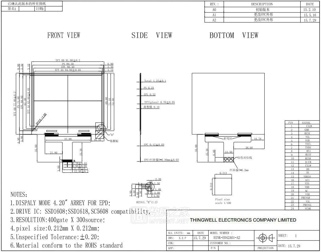
4.2“,400x300
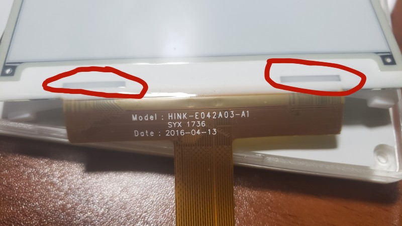
HINK-E042A03-A1
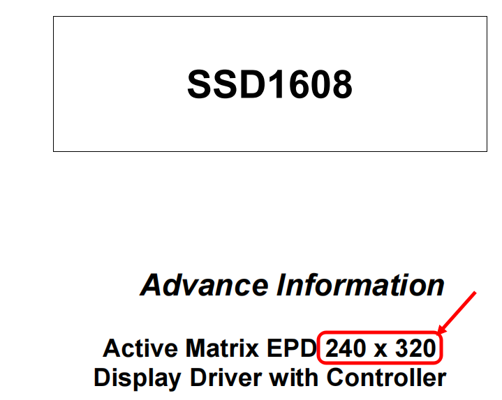
Drive IC:ssd1608


This screen has 2 CS pins, so the board needs to be modified.
The source code comes from the website.
I haven't tested this code yet, so I'll record it and try it when I have time.
const uint8_t EPD_lut[30]={
  0x66, 0xa6, 0x6a, 0x66, 0x55, 0x99, 0xaa, 0x66,
  0x55, 0x95, 0xaa, 0xaa, 0x59, 0x55, 0xaa, 0x55,
  0x88, 0x11, 0x11, 0x88,
  0xf8, 0xff, 0xff, 0xff, 0xff, 0xff, 0xff, 0xff,
  0x8f, 0x8f,
};

void init()
{
  EPD_RST_LOW;
  delayMS(10);
  EPD_RST_HIGH;
  delayMS(10);
  EPD_CS1_LOW;
  EPD_CS2_LOW;
  EPD_WriteCMD(0x12);
  while(EPD_isBusy());
  EPD_WriteCMD3DAT(0x01, 0x2b, 0x01, 0x00);
  EPD_WriteCMD1DAT(0x3a, 0x16);
  EPD_WriteCMD1DAT(0x3b, 0x08);
  EPD_WriteCMD1DAT(0x21, 0x83);
  EPD_WriteCMD1DAT(0x3c, 0x33);
  EPD_WriteCMD1DAT(0x11, 0x01);
  EPD_WriteCMD2DAT(0x44, 0x00, 0x18);
  EPD_WriteCMD4DAT(0x45, 0x00, 0x00, 0x2b, 0x01);
  EPD_WriteCMD1DAT(0x2c, 0xb9);
  EPD_WriteCMD(0x32);
  EPD_WriteMultiDAT(EPD_lut, 30);
  EPD_CS1_HIGH;
  EPD_CS2_HIGH;
}

void write_left(uint8_t *dat)
{
  EPD_CS1_LOW;
  EPD_WriteCMD1DAT(0x4e, 0x00);
  EPD_WriteCMD2DAT(0x4f, 0x00, 0x00);
  EPD_WriteCMD(0x24);
  EPD_WriteMultiDAT(dat, 7500);
  EPD_CS1_HIGH;
}

void write_right(uint8_t *dat)
{
  EPD_CS2_LOW;
  EPD_WriteCMD1DAT(0x4e, 0x00);
  EPD_WriteCMD2DAT(0x4f, 0x00, 0x00);
  EPD_WriteCMD(0x24);
  EPD_WriteMultiDAT(dat, 7500);
  EPD_CS2_HIGH;
}

void refresh()
{
  EPD_CS1_LOW;
  EPD_CS2_LOW;
  EPD_WriteCMD1DAT(0x22, 0xc7);
  EPD_WriteCMD(0x20);
  EPD_CS1_HIGH;
  EPD_CS2_HIGH;
  while(EPD_isBusy());
}

void sleep()
{
  EPD_CS1_LOW;
  EPD_CS2_LOW;
  EPD_WriteCMD1DAT(0x10, 0x01);
  EPD_CS1_HIGH;
  EPD_CS2_HIGH;
}

void main()
{
  init();
  write_left(...);
  write_right(...);
  refresh();
  sleep();
  while(1);
}
 MakerM0
Discussions
Become a Hackaday.io Member
Create an account to leave a comment. Already have an account? Log In.