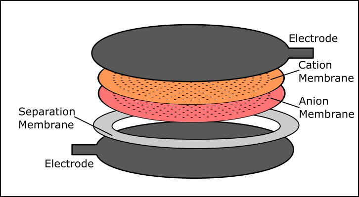
In an attempt to improve the efficiency, repeatability and ease of construction of the fuel cell, we decided to change our approach to the electrode assembly. As we described in the details for this project, two liquids on either side of the membrane are at a nonequilibrium steady state with respect to their boundary conditions. We added a flowback channel, and aim to have a diffusion rate less than that of the bipolar membrane so there is an appreciable pH difference remaining despite the diffusion.
The diffusion path allows recombination of ions and the production of an electric current, but the total path length of the particles must be minimized to make them more likely to take that path: the power of the device drops off exponentially with the path length of the particles, to the square of the distance between the electrodes, and proportionally to the surface area of the electrodes. In the previous setup, we had two small electrodes and one large flowback channel in the center, so that the particle path length may be as large as the radius of the entire device for the particle to make the trip from one electrode to the other, recombine and diffuse back through.
In order to minimize total path length for this otherwise improbable event, we created a series of small holes in the bipolar membrane instead of one large flowback hole. The holes, spaced 4 mm apart with a diameter between .2mm and .05mm depending on the tooling available, will serve as many small flowback channels. Overall this will allow for a larger effective surface area for the electrode as well, because flowback will be evenly spaced over the entire surface of the membrane. We hope this will show a marked improvement over other models, with the smaller path length translating into increased power output.
We are currently setting up a jig that will allow us to drill holes into the bipolar membrane using a .2 mm micro bit. Using a drill bit should minimize the disruption of the membrane interface over other methods such as piercing the membrane with pins.
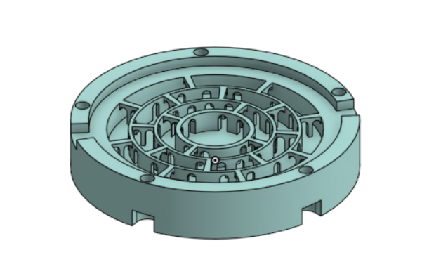
In addition to changing the membrane layers in the electrode assembly, there were some changes to the printed flow cell. We closed off the original center opening to the electrode assembly and added two notches opposite one another for the electrode tabs. Additionally we will be making an insertable frame so that the inside of the device can be lined with aquarium-grade silicone or parrafin wax, and an enclosure made of black PETG to keep light away from the device, in case any photocatalytic processes might serve as a source of energy for the device.
Discussions
Become a Hackaday.io Member
Create an account to leave a comment. Already have an account? Log In.