The pH gradient cells and the flow battery cells appear to work, although more data is needed to be certain. Currently we are moving the pH probe between the inside and outside cavity manually, which can cause calibration drift. It would be better if we had two pH probes, calibrated the same initially, so we could directly compare the pH inside and outside of the devices and show that they equilibrate differently at the same time. Using two pH probes would also control for any pH buffer solution that diffuses out of the pH probe tips, potentially causing pH readings to drift. Even without that though, the pH measurements are repeatably higher or lower depending on which direction the ion membrane faces.
There are two additional sources of error to watch out for. First, when the pH probe is rinsed with DI water or removed from the storage solution and placed in the pH gradient cell, it takes up to a few minutes for the probe to equilibrate with the solution. Second, after freshly mixing the liquid, the pH may differ on both sides due to accidental dissolution of gases like CO2 or due to the introduction of contaminants. Great attention must be taken when handling the liquid to ensure no contaminants are introduced.
Also as you will see, if fresh solution is used, it will need to equilibrate with the membrane over the course of hours - using fresh NaOH or NaCO3 solution is not advised once the devices are equilibrated: this could react with the active sites in the ionomer and clog them up if done too many times. For the effect to happen, there must be more unoccupied ionic functional groups on the bipolar membrane than there are ions in solution. If mixing the liquids to extinguish the pH gradient, you should re-mix the liquid already in the cells, and only use DI water to account for evaporation. This will ensure that the liquid is as equilibrated as possible with the device and help avoid contamination as well.
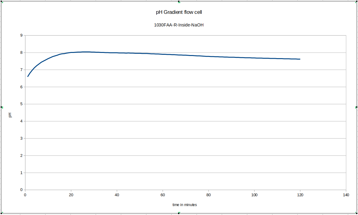
This was the first data acquisition of the pH gradient flow cell. You can see the initial effect of removing the probe from the storage solution and putting it in the test environment, and then you can see that since fresh NaOH solution was used instead of mixing the liquid in the device, longer-term equilibration was still happening. These drifts do not happen in later tests to anywhere close to this degree, once we start accounting for these effects in our experimental procedulre.
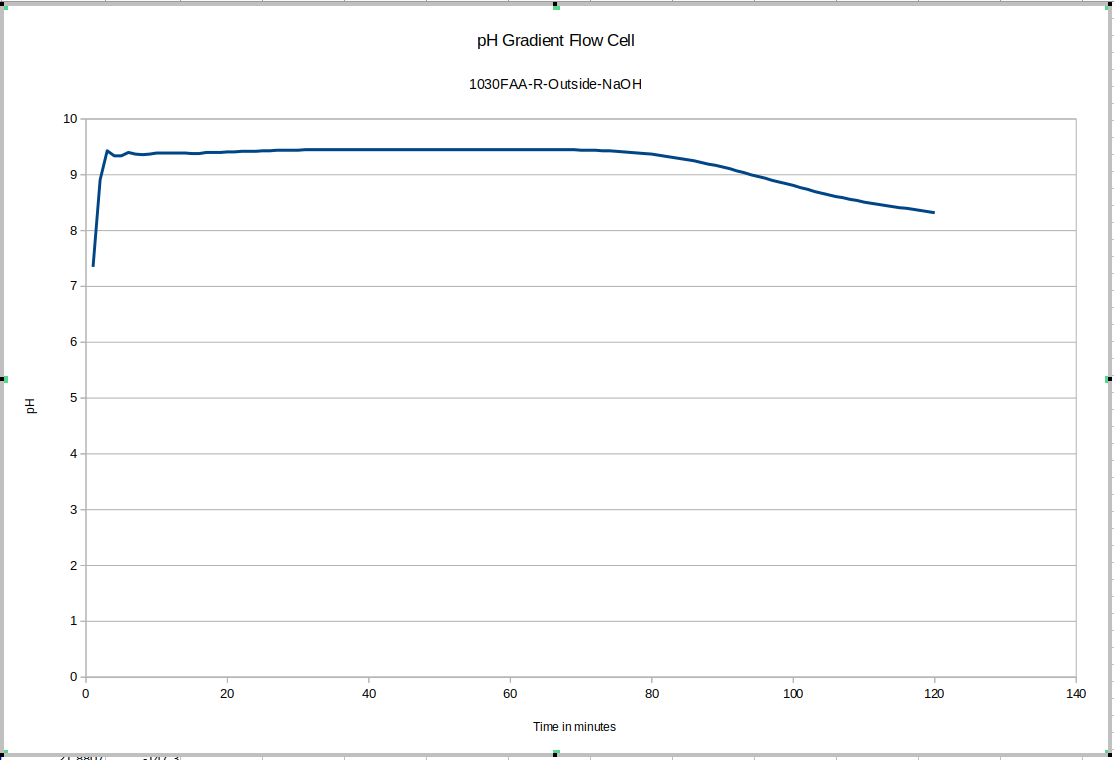
Here again you can see the effect of removing the device from the storage solution and putting it into the test device: this time it is much quicker for some reason: more investigation may be warranted to explain that: it may depend on whether or not the probe was rinsed of storage solution before adding it to the test environment. This test drifts a bunch too: since our maximum pH buffer is 10, it's possible it's not reading properly during the earlier part of the test. This liquid was still equilibrating with the new NaOH solution: we recommend letting everything equilibrate for a few days before beginning testing, and reusing the fluid inside the test device, topping it up with DI water only.
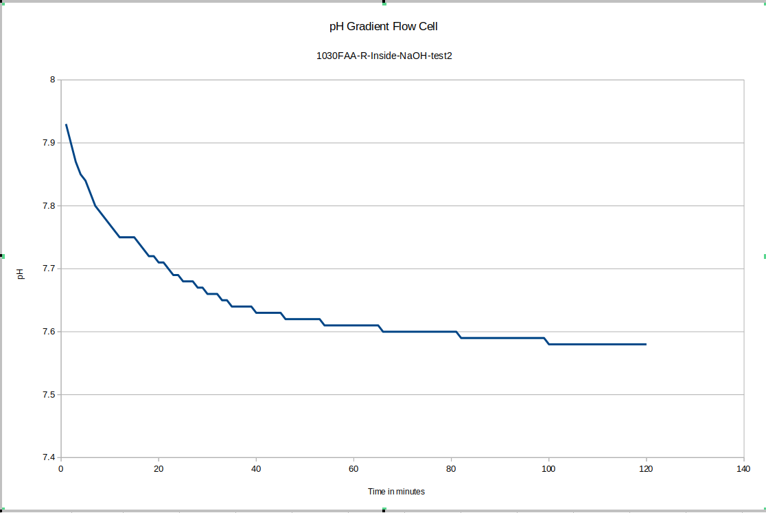
Once we began to account for the sources of error in the first few tests, we started to get data that drifted much less after an initial equilibration period.
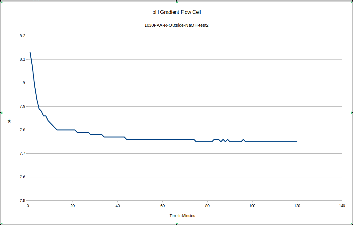
For our test device "R" the outside equilibrated to about 7.75 and the inside equilibrated to about 7.58. This is good because as you will see, the test device "L" has its membrane direction reversed relative to "R", and it tends to have the higher pH on the inside.
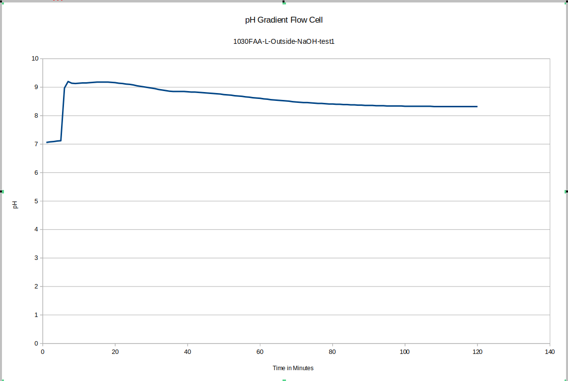
In this test, the test was started in both cases while the pH probe was in its storage solution. hence the large initial disruption.
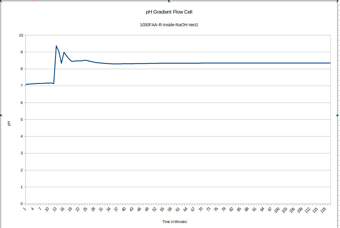
Unfortunately, this makes it a little difficult to see, but the inside seems to have a steady-state pH which is about 0.1 higher than the outside, which is the same order of magnitude that we saw in test device "R", which had a pH difference of .17.
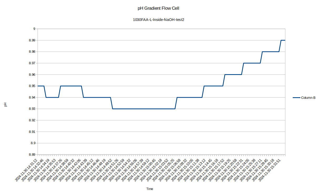
After that test I decided I would try to start the tests after the pH probe was in place in the test environment. I still sometimes caught the tail end of it, but these graphs came out clearer.
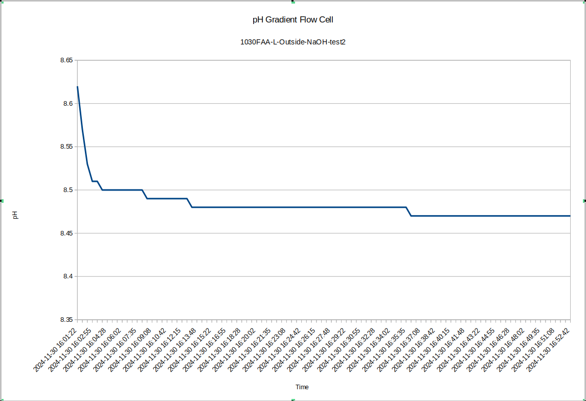
Also for test 2 here I left the device to equilibrate overnight, so the pH difference between the inside and the outside is now very large: about 0.52 with the inside being higher, which is consistent with the previous data.
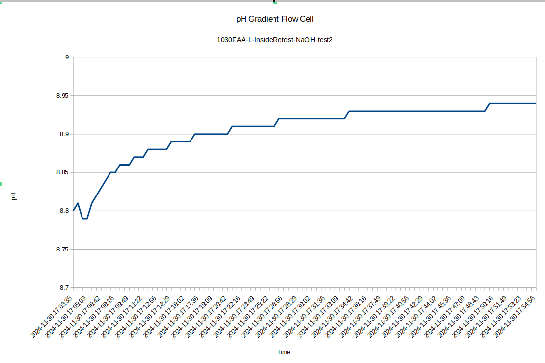
I was surprised to see such a large difference between the inside and outside pH, so I re-tested the inside of the device to see how repeatable the measurements were with the pH probe: I got a measurement of 8.94, so the measurement error seems to be down around .05, which is 10 times less than the pH difference we are seeing!
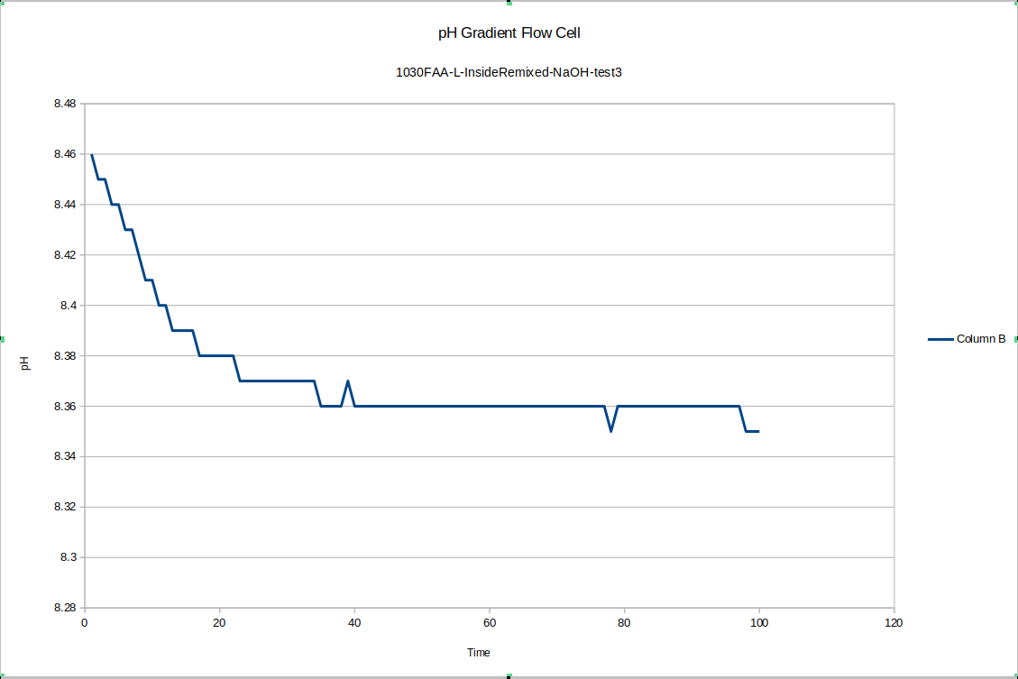
For one final pH gradient test, I remixed the liquid on the inside and outside of device "L" and ran one more test. It seems the slower equilibration may happen after the liquid in the devices is freshly mixed. In any case, a short time after re-mixing the inside quickly stabilized at 8.35
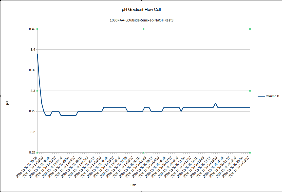
And the outside stabilized at 8.26, with a difference of .09 right after mixing - a little small if the measurement error between those previous tests was .05, but if we let the device equilibrate overnight again, I expect the pH difference will go back up around .5 again. Other similar results exist elsewhere in the literature for pH gradients across bipolar membranes: the bipolar membrane setup on its own does not constitute a nonequilibrium steady state, but one could certainly imagine punching sufficiently small holes in the membrane so that it must do work against the flowback to maintain the pH gradient. So that's tested by our new flow cell design.
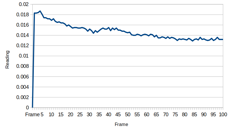
When moved to the test site, a little charge built up which subsequently dissipated: it seems the device gains a little bit of energy from macroscopic turbulence in the water. The voltage stabilizes at about 0.0135 millivolts after a while. The flowback holes provide an electrical resistance that the system works against, and the exponential behavior is related to the capacitance between the two electrodes. We will need to measure that resistance and capacitance to know just how much energy is actually here, but that will introduce energy to the circuit, so we want to take all these measurements first before getting the capacitance and resistance values.
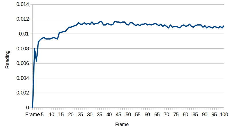
Once the device is shorted, the energy returns, and always in the same direction. Clearly some chemical energy is drained when this happens, as in this case the voltage only went back up to 0.0125 millivolts, but if we wait to the following day, the device always replenishes itself.
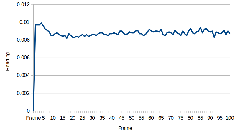
After shorting the device again, it holds steady at about 0.09 millivolts. Another thing to note was the temperature in the room cooled down by a few degrees towards the end of the day, and this could also contribute to the voltage reduction. These data are very preliminary and more work is needed to characterize the system behavior better.
 Michael Perrone
Discussions
Become a Hackaday.io Member
Create an account to leave a comment. Already have an account? Log In.