Tube sockets (also known as valve sockets) come in two main forms: chassis mounting which is where you make a circular hole in a metal chassis and fasten the socket to it, or breadboard mounting where you fasten the tube socket to a wooden breadboard. The majority of tube sockets are chassis mounting because the metal chassis helps screening between circuits. But the breadboard mounted sockets are easier to work with because you don't have to make a large circular hole. Here they are:
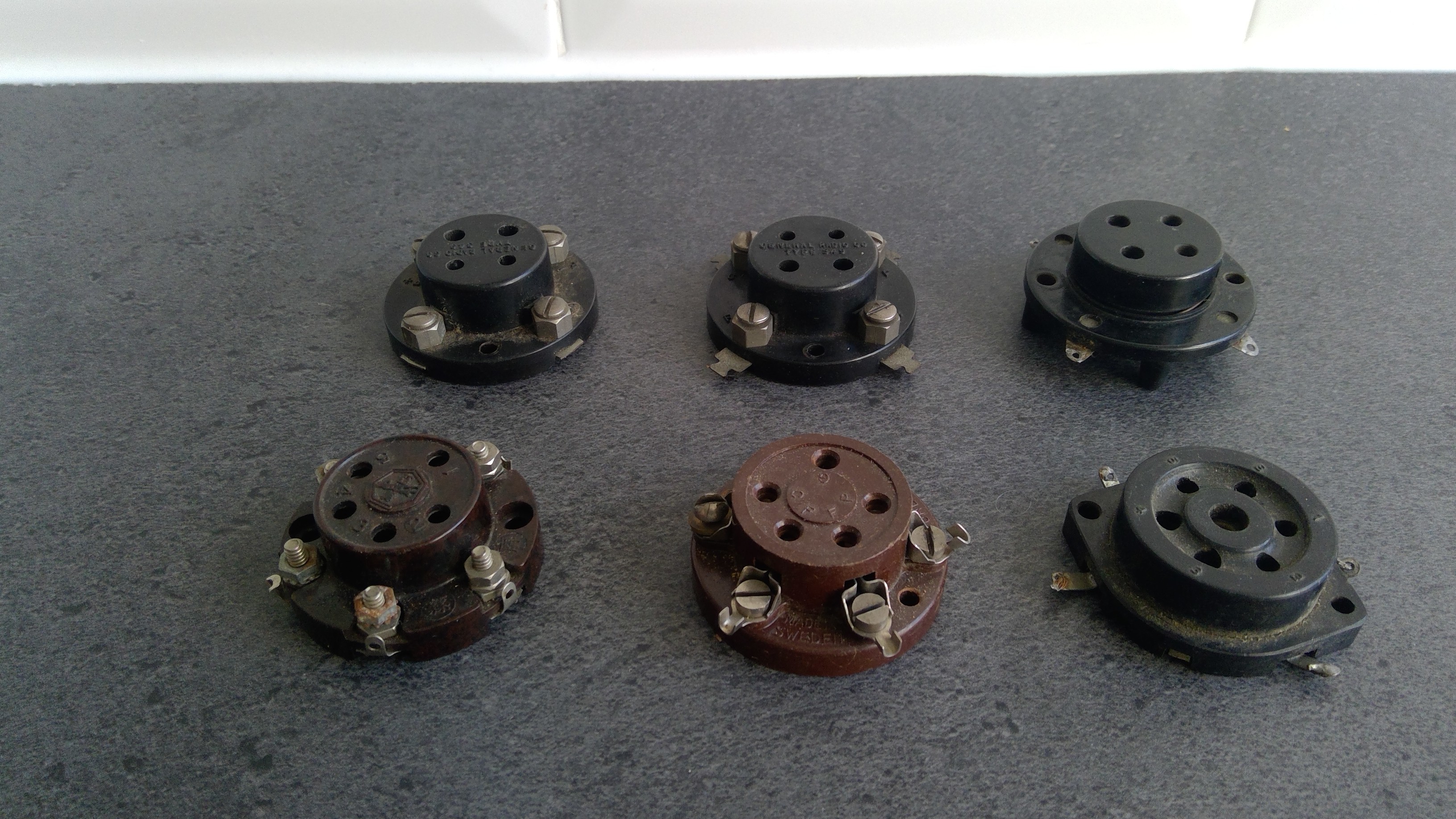
You can see the 4 pin sockets at the back of the photo, and the 5 and 6 pin sockets at the front. These were difficult to find, and if you're building this project it's perfectly fine to use chassis mounting sockets and spacers, to hold the socket above the breadboard. But I think the breadboard sockets look better.
The 4-pin sockets are called UX-4, the 5-pin UY-5 and I think the 6-pin is UZ-6. Actually I'm not sure about the last two, you could probably call them UX-4, UX-5 and UX-6.
In early radio construction you didn't need a soldering iron because the sockets used thumb screws and the circuit could be built by wrapping solid core wire around the thumb screws and nuts and bolts. But I couldn't find any using thumb screws so I will have to use the soldering iron.
Discussions
Become a Hackaday.io Member
Create an account to leave a comment. Already have an account? Log In.