Hey folks got a lot to update everyone on this project since I last posted about it ! So even though I haven't updated this page in a while I have been working on the project in some way shape or form! Over the summer I was able to devote a lot more time to the project and make considerable progress. In the spring we aquired all the components on the BOM for the JoyStick-HID part of the project. Around July tweaks were made to the PCB the boards were ordered and a few additional BOM items were procured !!
Anyways talk is cheap here's the pix:
Raw PCB from OSHPark.com go check them out for your PCB needs !
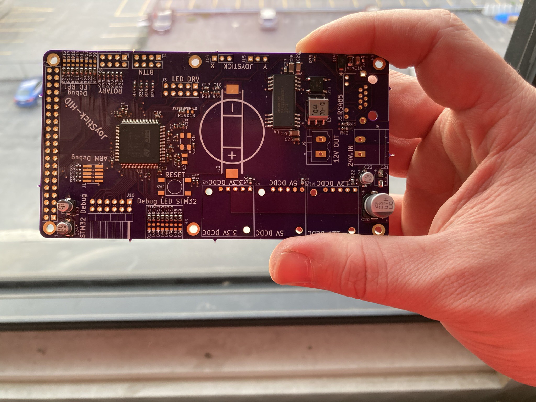
Partially assembled during sunset !
Fully Assembled (as much as it could be fully assembled)
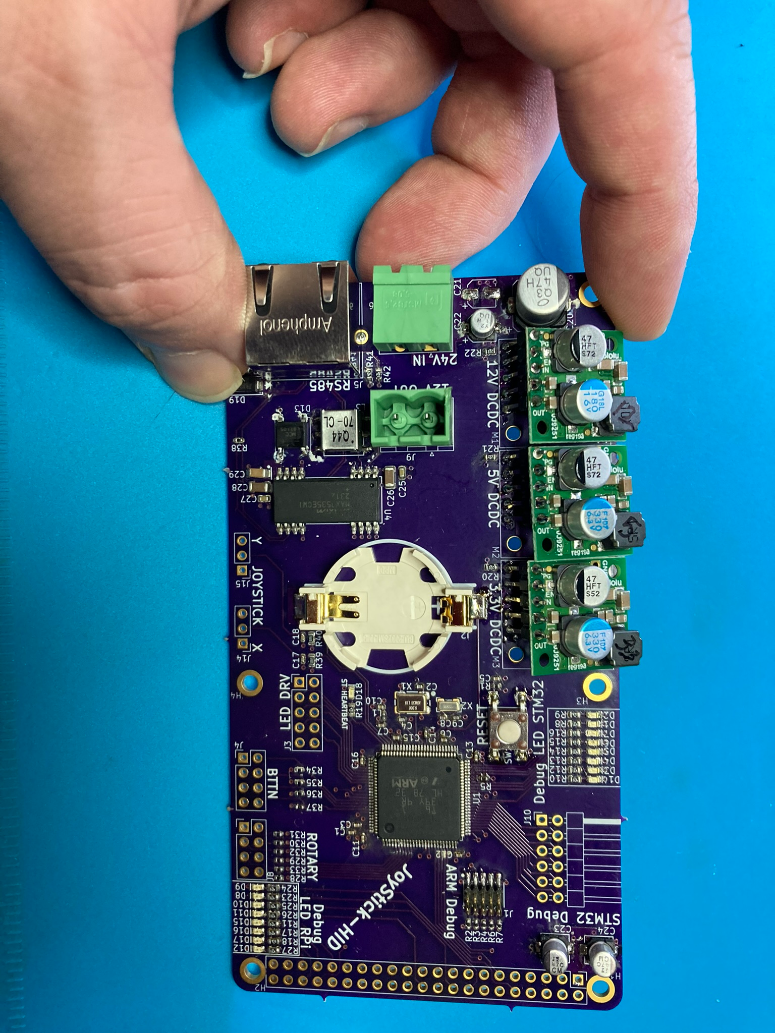
Assembly
The assembly of the JoyStick-HID PCB went fairly smoothly. A few errors were disovered along the way. The holes for the pin headers for the DCDC regulator modules were too small, they had to be carefully grafted onto the PCB with solder. This happens with PCB design you're bound to make silly mistakes like this.
Assembly issues totaled out:
- Footprint for Raspberry Pi Header connector is wrong, its 42 pins should be 40
- 10uF caps on input = footprint too small!
- C19 footprint too big
- Max chip Pin 1 legend too hard to see
- RS485 diode orientation legend not on PCB
- STM32 Pin 1 legend not there
- Header holes for DCDC regulator modules too small had to hack them on there.
- ARM Cortex M Debug Connector issues, signals are flipped around, the footprint numbering doesn't correspond to the symbol numbering.
- All DCDC Regulators Work and produce correct voltage
- Debug LEDs Work
- GPIO and ADC Interfaces Work
The biggest issue with assembly and testing was the programming interface pins were flipped. This too a lot of debugging and testing different things to figure out why the chip was not connecting to the programmer. I've designed around this MCU many times over the years but I noticed that the connector used for the cortex M Debug interface wasn't always the same and I made new footprints for new components added to my library. These days a lot of the premade parts are fairly accurate I usually download them and manually check them and make some adjustments. What I did notice on this connector was the pin numbering was flipped on the footprint vs he symbol flipping the connector signal layout.
The way round this was to solder in the programmer:
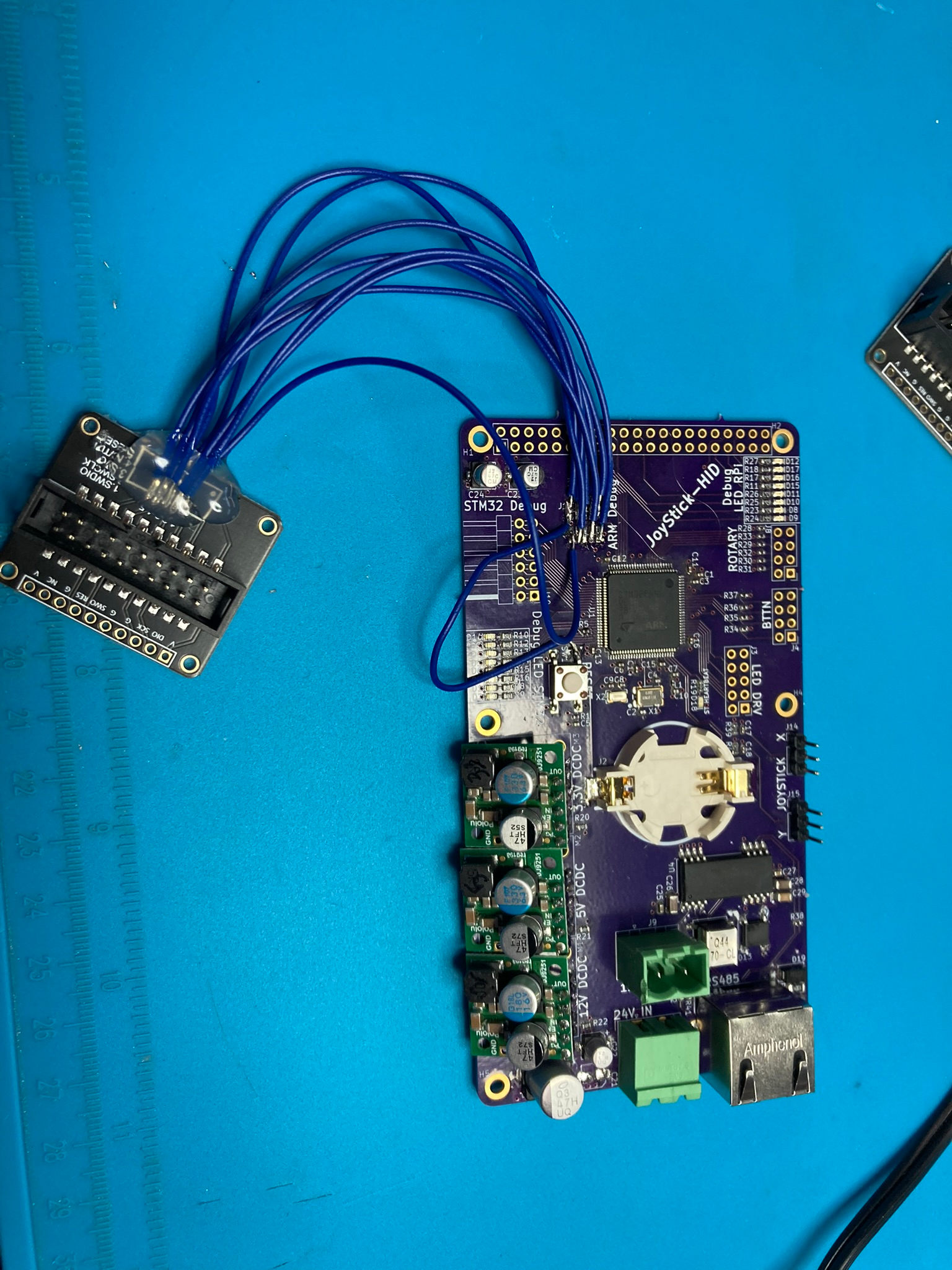
Hooked up to Programmer (ST-Link V2)

Up And Running:

Firmware for testing was written in C using STM32CUBEIDE and STM32CUBEMX for port mapping and initialization code generation. Demo code can be found here: https://github.com/Accessibilita/JoyStick-hat-firmware
Demo of code running:
During the assembly of the JoyStick-HID a separate analysis of the RPi 5 was carried out, since the plan was to have the JoyStick-HID be a RPi hat and have the RPi 5 do advanced functions like interface with USB HID devices as alternative control input or interface with battery's that use bluetooth for information reporting. The RPi5 was deemed too hot for a sealed enclosure. The JoyStick-HID when enclosed has to be effectively water proof we are shooting for IP67/IP68. While I assembled the first JoyStick-HID I started redesigning the new version. I eliminated the RPi5 early on in the redesign after discussing with the rest of the team. Instead we are going to design a separate module that contains an RPi5 a hat with dual RS485 interfaces all housed in an enclosure with a passive heatsink sealed, but that's for another project log.
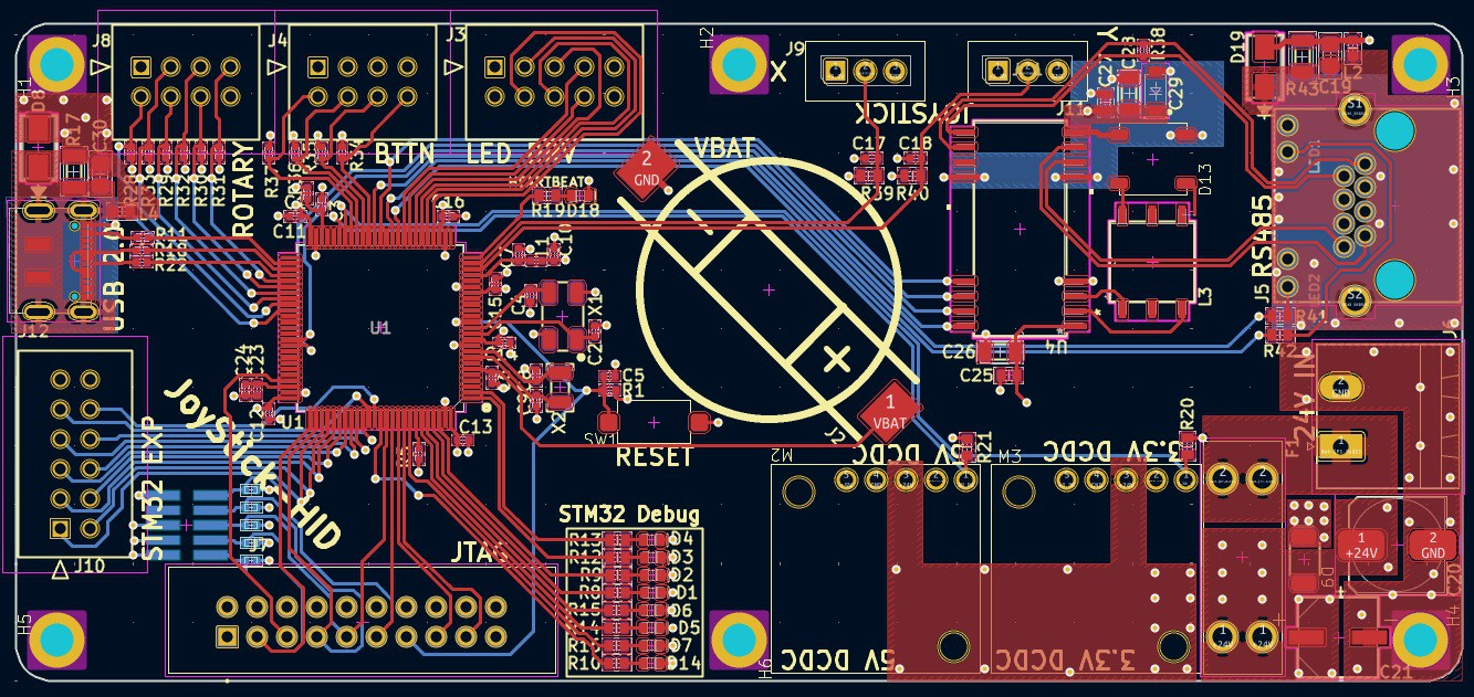
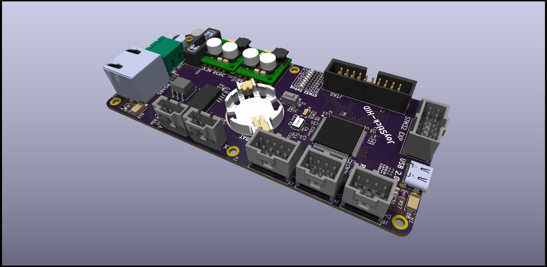
Anyways version 0.2a of the JoyStick-HID is based entirely around the STM32F44VET6 MCU the formfactor of the PCB is still RPi inspired in terms of shape and hole spacing, board is still 4 layers. Notable changes other than RPi are removal of 12V regulator as we don't need it, addition of 20 pin ARM JTAG, fuse and crobar circuit, and all connectors swapped over to locking clipped versions.
Enjoy the renders:
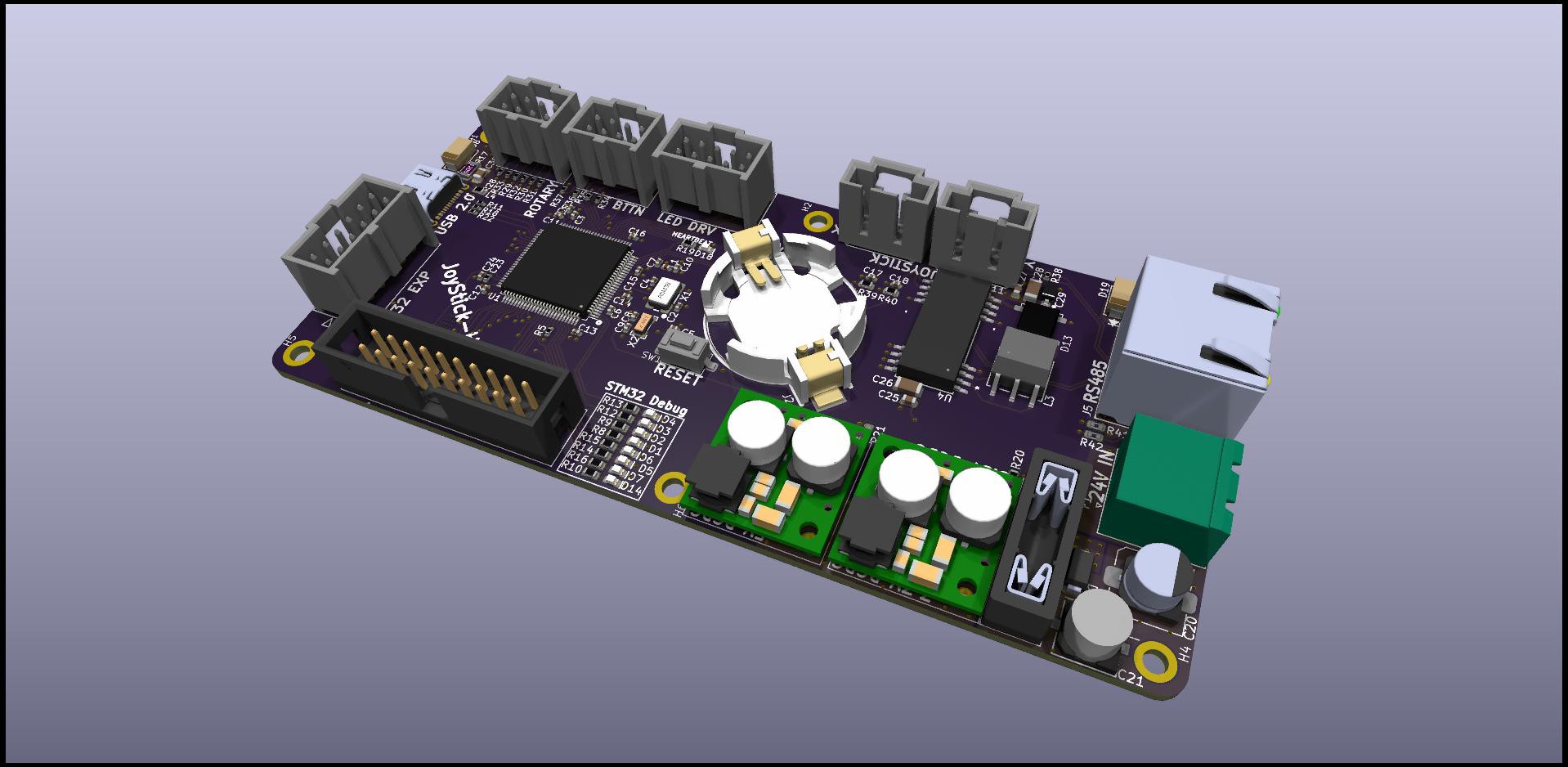

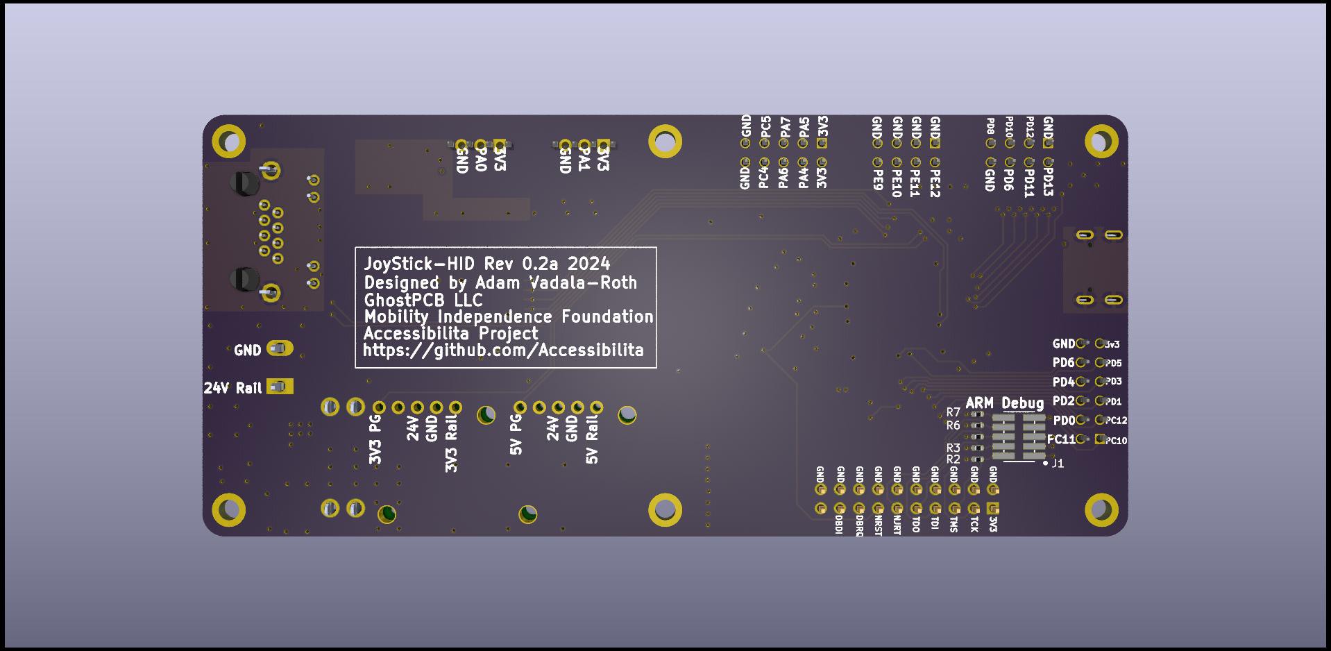
That's it for the JoyStick-HID ! We are going to push ahead with V2 since the programming interface that had to be soldered together isn't reliable and continually breaks down. There is still more testing to do but for the most part all he necessary peripherals we are using are initializing and working. GPIO is definitely working but we need to test RS485 and analog inputs. Waiting on a jig from another engineer in the project to test the RS485 so I need that before I can finish testing. Still I want to push forward with a 2nd rev so I can work on software more reliably since hardware is pretty basic and I don't think there will be many bugs or changes in the next version.
As always the source for all these boards and designs is on Github.com the links to which are on the project page and below:
https://github.com/Accessibilita/Joystick-Hat
https://github.com/Accessibilita/JoyStick-hat-firmware
Stay tuned for the next update coming soon !
 AVR
AVR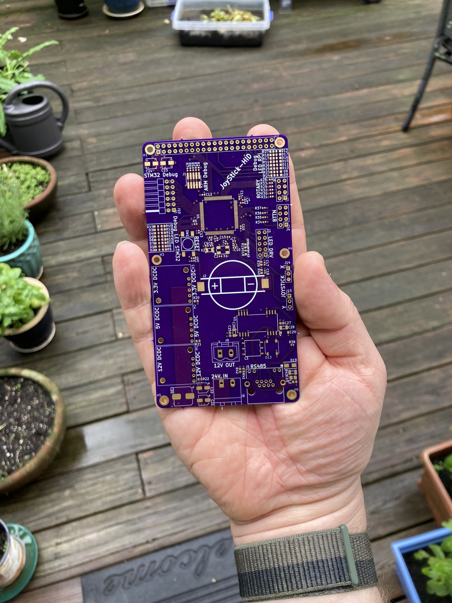
Discussions
Become a Hackaday.io Member
Create an account to leave a comment. Already have an account? Log In.