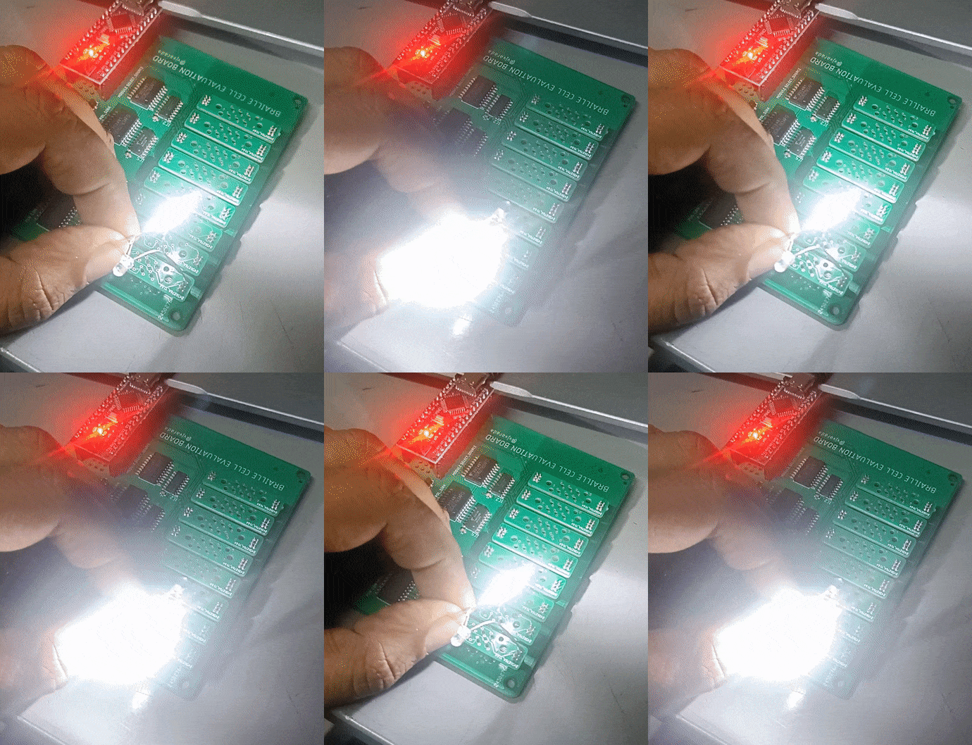
I tested out the driving electronics using two LEDs connected in opposing polarities, and adjusting the LM317 output to bring down the voltage so as not to burn the LEDs out.

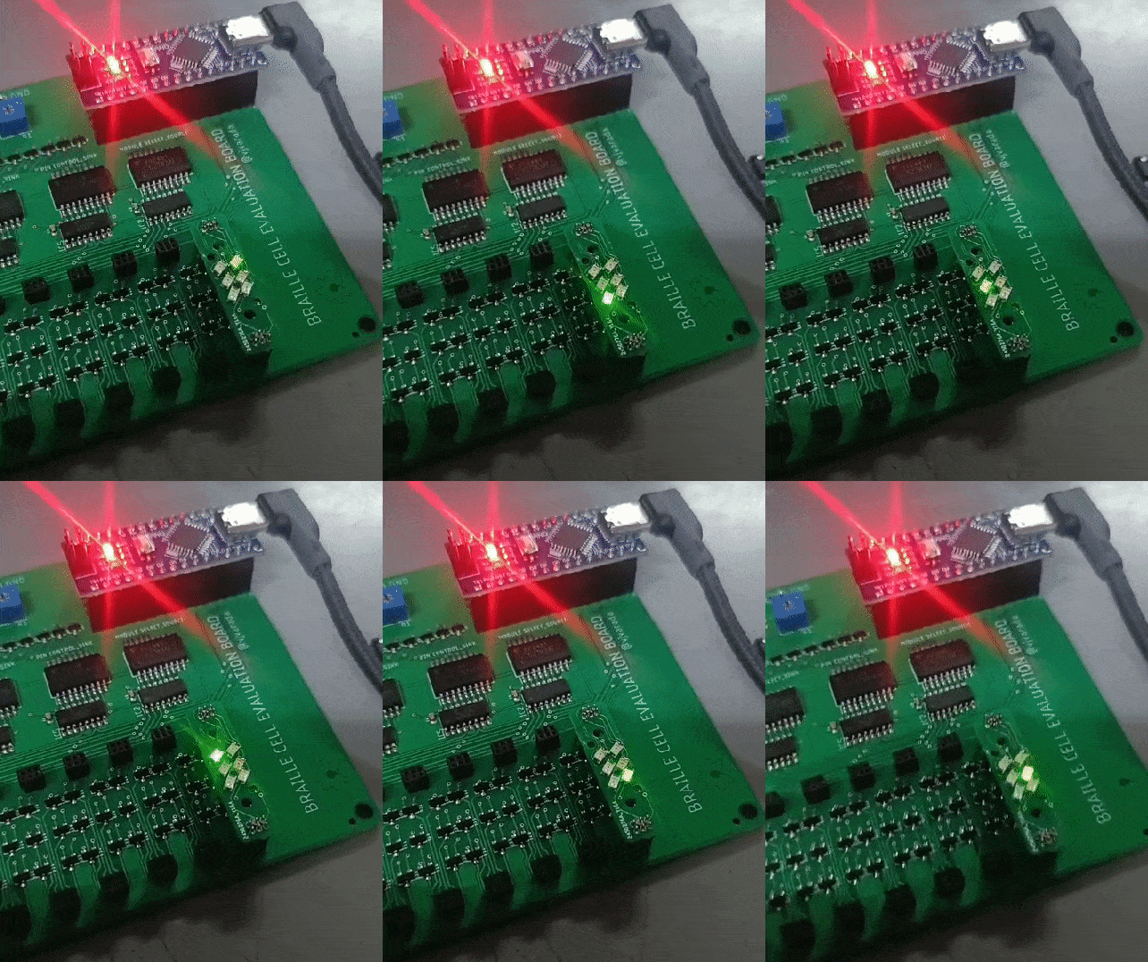
This is what the code looks like running. The via placement for the coils just happened to be the right size to mount a few 0603 package SMD LEDs, so I converted one of the braille module PCBs into a tester.

The code below shows the functions I'm using to select which pin of which module to actuate. MOD_X and PIN_X are the pin numbering for the input pins of the decoder IC.
void moduleSelect(int decimalValue) {
  //Ensure the input decimal value is within the valid range (1 to 8)
  //numbering starts from 1, so subract
  decimalValue--;
  if (decimalValue >= 0 && decimalValue <= 7) {
    // Calculate the binary representation of the decimal value
    digitalWrite(MOD_0,(decimalValue >> 0) & 0x01);
    digitalWrite(MOD_1,(decimalValue >> 1) & 0x01);
    digitalWrite(MOD_2,(decimalValue >> 2) & 0x01);
  } else {
    digitalWrite(MOD_0,0);
    digitalWrite(MOD_1,0);
    digitalWrite(MOD_2,0);
  }
}

void pinSelect(int decimalValue) {
  //Ensure the input decimal value is within the valid range (1 to 6)
  //numbering starts from 1, so subract
  decimalValue--;
  if (decimalValue >= 0 && decimalValue <= 5) {
    // Calculate the binary representation of the decimal value
    digitalWrite(PIN_0,(decimalValue >> 0) & 0x01);
    digitalWrite(PIN_1,(decimalValue >> 1) & 0x01);
    digitalWrite(PIN_2,(decimalValue >> 2) & 0x01);
  } else {
    digitalWrite(PIN_0,0);
    digitalWrite(PIN_1,0);
    digitalWrite(PIN_2,0);
  }
}
After the pin/module is selected, the enable pins of the decoder IC are manipulated to change the polarity of the voltage across each pin.
void pinSet() {
  digitalWrite(SET,1);
  digitalWrite(RESET,0);
}

void pinReset() {
  digitalWrite(SET,0);
  digitalWrite(RESET,1);
}

void pinOff() {
  digitalWrite(SET,0);
  digitalWrite(RESET,0);
}
The whole code to test out the addressability of the pins is below:
// Pin configuration
const int MOD_0 = 6;   // A0, A1, A2 of the 1st decoder
const int MOD_1 = 7;
const int MOD_2 = 8;

const int PIN_0 = 9;   // A0, A1, A2 of the 2nd decoder
const int PIN_1 = 10;
const int PIN_2 = 11;

const int RESET = 5;  // Set pin of the 1st decoder
const int SET = 4;  // Reset pin of the 1st decoder


void setup() {
  // Initialize Serial communication for debugging (optional)
  Serial.begin(9600);
  pinMode(MOD_0,OUTPUT);
  pinMode(MOD_1,OUTPUT);
  pinMode(MOD_2,OUTPUT);

  pinMode(PIN_0,OUTPUT);
  pinMode(PIN_1,OUTPUT);
  pinMode(PIN_2,OUTPUT);

  pinMode(SET,OUTPUT);
  pinMode(RESET,OUTPUT);
}

void loop() {
    moduleSelect(1);
    int pin = 1;
    while(true)
    {
        pinSelect(pin);
        pinSet();
        delay(500);
        pinReset();
        delay(500);
        pinOff();
        delay(500);
        pin++;
        if(pin > 6)
        {
            pin = 1;
        }
    }


}

void moduleSelect(int decimalValue) {
  //Ensure the input decimal value is within the valid range (1 to 8)
  //numbering starts from 1, so subract
  decimalValue--;
  if (decimalValue >= 0 && decimalValue <= 7) {
    // Calculate the binary representation of the decimal value
    digitalWrite(MOD_0,(decimalValue >> 0) & 0x01);
    digitalWrite(MOD_1,(decimalValue >> 1) & 0x01);
    digitalWrite(MOD_2,(decimalValue >> 2) & 0x01);
  } else {
    digitalWrite(MOD_0,0);
    digitalWrite(MOD_1,0);
    digitalWrite(MOD_2,0);
  }
}

void pinSelect(int decimalValue) {
  //Ensure the input decimal value is within the valid range (1 to 6)
  //numbering starts from 1, so subract
  decimalValue--;
  if (decimalValue >= 0 && decimalValue <= 5) {
    // Calculate the binary representation of the decimal value
    digitalWrite(PIN_0,(decimalValue >> 0) & 0x01);
    digitalWrite(PIN_1,(decimalValue >> 1) & 0x01);
    digitalWrite(PIN_2,(decimalValue >> 2) & 0x01);
  } else {
    digitalWrite(PIN_0,0);
    digitalWrite(PIN_1,0);
    digitalWrite(PIN_2,0);
  }
}

void pinSet() {
  digitalWrite(SET,1);
  digitalWrite(RESET,0);
}

void pinReset() {
  digitalWrite(SET,0);
  digitalWrite(RESET,1);
}

void pinOff() {
  digitalWrite(SET,0);
  digitalWrite(RESET,0);
}
 Vijay
Vijay
Discussions
Become a Hackaday.io Member
Create an account to leave a comment. Already have an account? Log In.