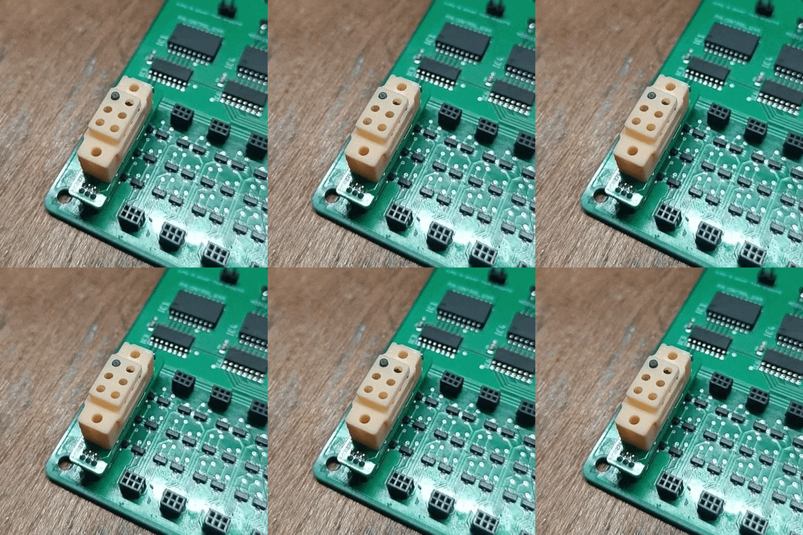
A couple of logs back, we tested the overall mechanism working with a single dot in isolation with the PCB designed and then verified that the PCB boards designed were working with LEDs
Now it's time to assemble them to see if the designed electronics can successfully drive at least one braille dot.

And it works! The assembly process for the braille module can be found in the instructions, so check it out there.
// Pin configuration
const int MOD_0 = 6;   // A0, A1, A2 of the 1st decoder
const int MOD_1 = 7;
const int MOD_2 = 8;

const int PIN_0 = 9;   // A0, A1, A2 of the 2nd decoder
const int PIN_1 = 10;
const int PIN_2 = 11;

const int RESET = 5;  // Set pin of the 1st decoder
const int SET = 4;  // Reset pin of the 1st decoder


void setup() {
  // Initialize Serial communication for debugging (optional)
  Serial.begin(9600);
  pinMode(MOD_0,OUTPUT);
  pinMode(MOD_1,OUTPUT);
  pinMode(MOD_2,OUTPUT);

  pinMode(PIN_0,OUTPUT);
  pinMode(PIN_1,OUTPUT);
  pinMode(PIN_2,OUTPUT);

  pinMode(SET,OUTPUT);
  pinMode(RESET,OUTPUT);
}

void loop() {
  pinSelect(1);
  moduleSelect(1);
  while(true)
  {
    pinSet();
    delay(50);
    pinOff();
    delay(1000);
    pinReset();
    delay(50);
    pinOff();
    delay(1000);
  }

}

void moduleSelect(int decimalValue) {
  //Ensure the input decimal value is within the valid range (1 to 8)
  //numbering starts from 1, so subract
  decimalValue--;
  if (decimalValue >= 0 && decimalValue <= 7) {
    // Calculate the binary representation of the decimal value
    digitalWrite(MOD_0,(decimalValue >> 0) & 0x01);
    digitalWrite(MOD_1,(decimalValue >> 1) & 0x01);
    digitalWrite(MOD_2,(decimalValue >> 2) & 0x01);
  } else {
    digitalWrite(MOD_0,0);
    digitalWrite(MOD_1,0);
    digitalWrite(MOD_2,0);
  }
}

void pinSelect(int decimalValue) {
  //Ensure the input decimal value is within the valid range (1 to 6)
  //numbering starts from 1, so subract
  decimalValue--;
  if (decimalValue >= 0 && decimalValue <= 5) {
    // Calculate the binary representation of the decimal value
    digitalWrite(PIN_0,(decimalValue >> 0) & 0x01);
    digitalWrite(PIN_1,(decimalValue >> 1) & 0x01);
    digitalWrite(PIN_2,(decimalValue >> 2) & 0x01);
  } else {
    digitalWrite(PIN_0,0);
    digitalWrite(PIN_1,0);
    digitalWrite(PIN_2,0);
  }
}

void pinSet() {
  digitalWrite(SET,1);
  digitalWrite(RESET,0);
}

void pinReset() {
  digitalWrite(SET,0);
  digitalWrite(RESET,1);
}

void pinOff() {
  digitalWrite(SET,0);
  digitalWrite(RESET,0);
}
The above is the code I used to figure out the ideal on/off time, and 50ms seems to be a safe enough time for the pin to actuator.
The next big thing to test is multiple dots working together, and see how the magnets interfere with each other, and if that causes any issues.
 Vijay
Vijay
Discussions
Become a Hackaday.io Member
Create an account to leave a comment. Already have an account? Log In.