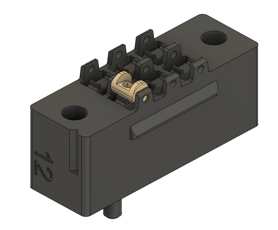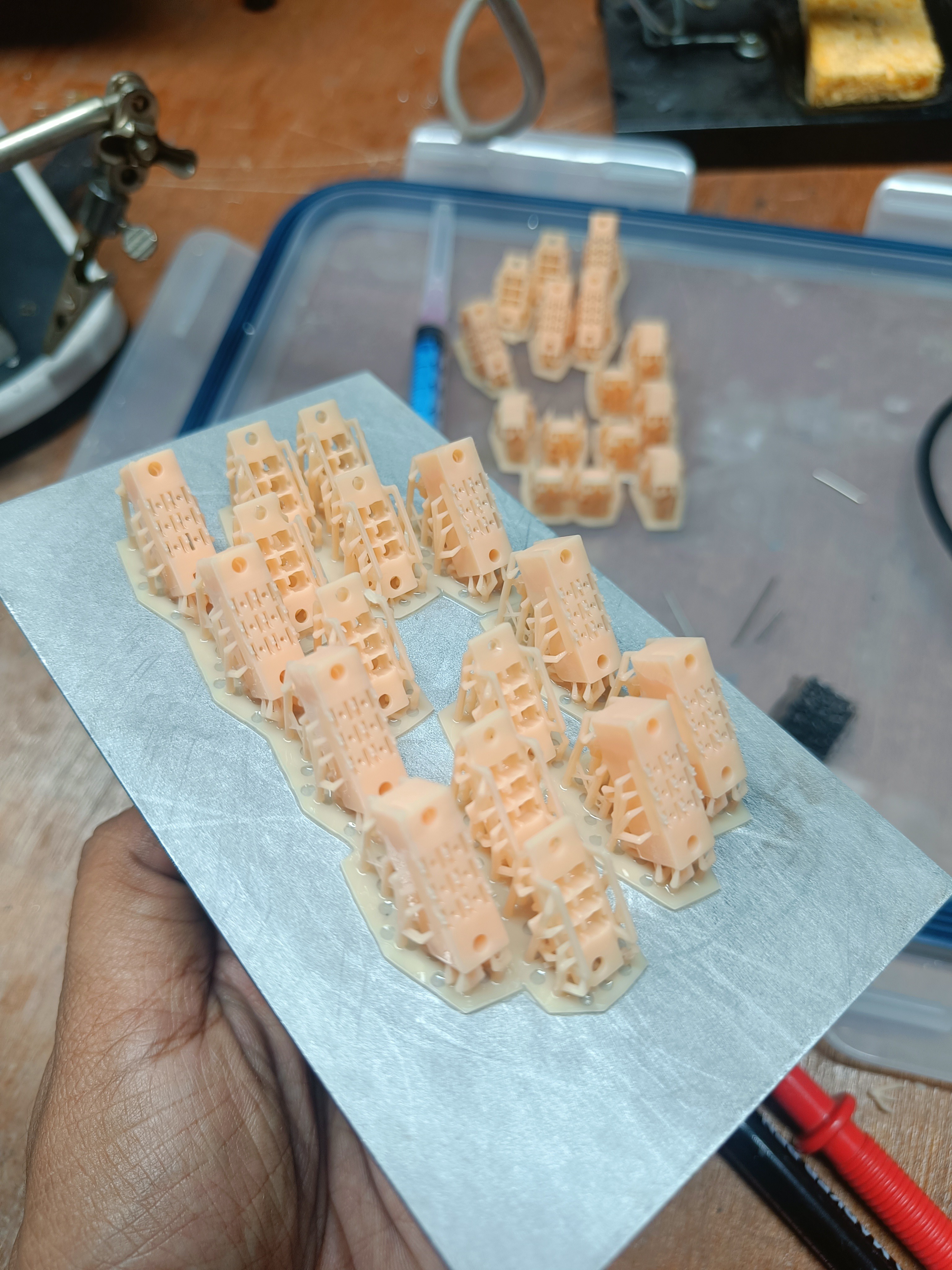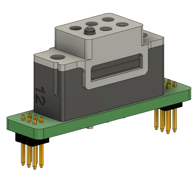
Having access to a printer directly made all the difference when iterating for 20-30 um tolerances. At these sizes, you can't really trust the CAD software anymore, and every assembly has to be empirically tested by printing it out.
In the final few iterations, I made the Cam assembly with the Braille Lower assembly independent of the Braille Upper, so that I could laser into the hole-shaft tolerance needed between the cam shaft and the hole it fit into.

Depending on the Resin, and printer used to print, I suspect the tolerances in the CAD design may need to be altered. Ive linked the final (so far) of the Braille Cell design below for FUsion 360. You should be able to navigate to the design history and change the hole size as needed if the cam is having a hard time fitting, or is too loose.

V12 CAD designs can be found here.
 Vijay
Vijay
Discussions
Become a Hackaday.io Member
Create an account to leave a comment. Already have an account? Log In.