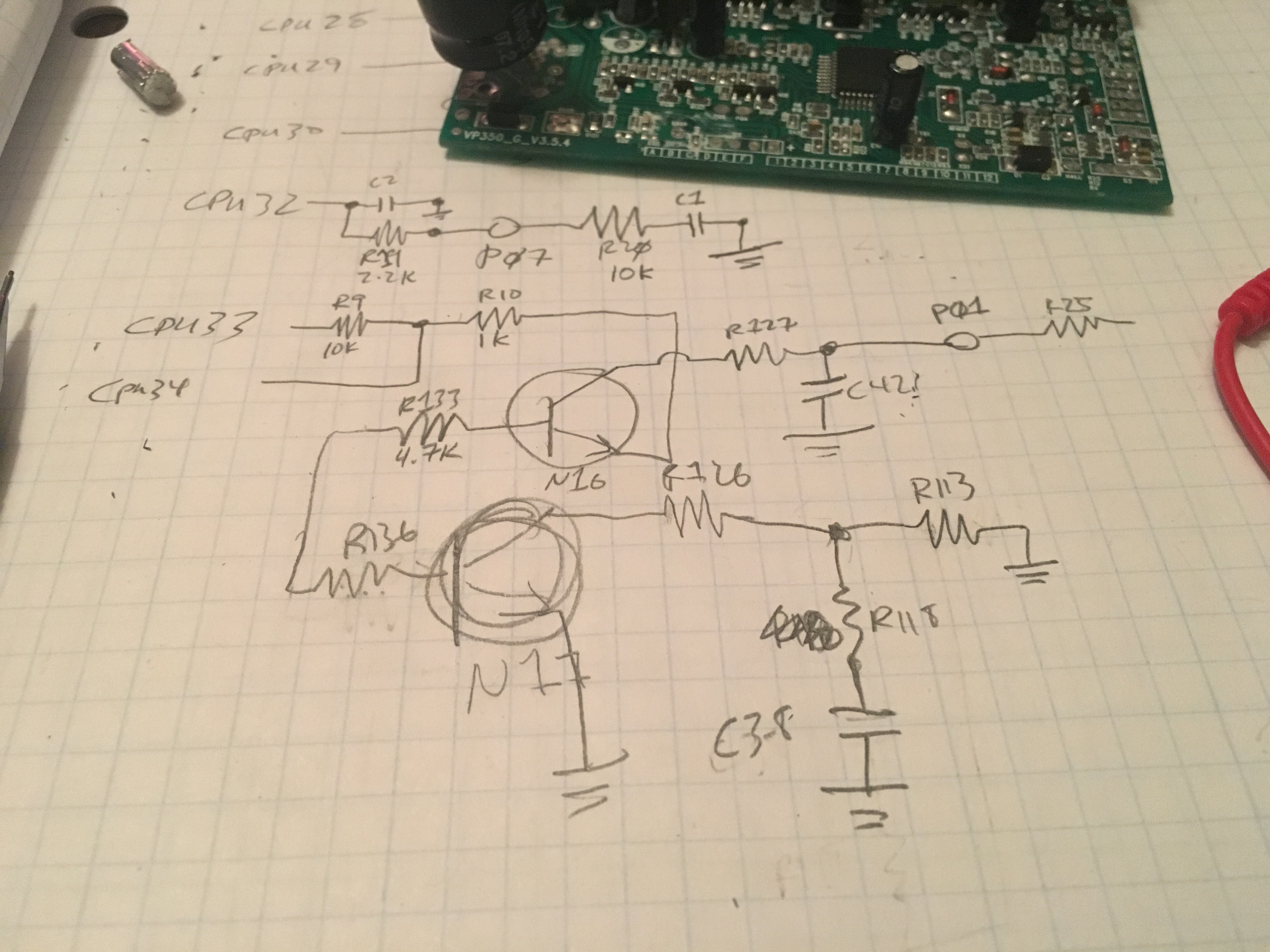
Yesterday I spent significant time drawing out the schematic of this nameless controller. (Yes, I should probably stop calling it "nameless" because it clearly has a label. In Chinese. But as far as I can tell, its name is "potted plant; not fermenting jug but similar; some sort of house; one" which doesn't do it justice either. So until someone translates it for me, "nameless" they shall remain.)
I stared with some web searching - has anyone reverse engineered this controller before? - which is a bit difficult when you're searching for "schematics for the potted plant not fermenting jug but similar" nameless controller. But I did wander across a reverse engineered ku63 controller, which is certainly along the same lines. As the guy says on his web page: "Here is the schematic of the KU63 motor controller which may also give insight into other Chinese motor controllers." Because, as he says, it seems common to have multiple very similar products coming from China that share just about the same schematic. So how close is it?
In some ways, it's fairly close. Eventually I'll import what I traced out in to Eagle and draw it up properly. Until then, this textual description will have to do.
The power stages use a different MOSFET but the design is very close. There are a couple places in the power system where this newer controller has obviously tried to improve reliability. There are other places where they've clearly optimized for cost (reducing part count, particularly around the throttle). And this nameless controller doesn't have the back-EMF circuitry that the KU63 does.
Overall, the KU63 work was good enough to give me a head start. It only took about 6 hours to trace out the majority of the circuitry; when I started wondering what the mystery circuitry was for (seriously, there are pins on the CPU that have capacitors directly to ground and naught else - why? - and then there are the transcription errors that show transistor bases connected to other transistor bases for pieces of circuitry that I have no clue why the exist!) I decided to stop decoding and move on to "can I get this to do anything?"
So, if I want to be the CPU, then I guess I gotta get rid of the CPU, eh?
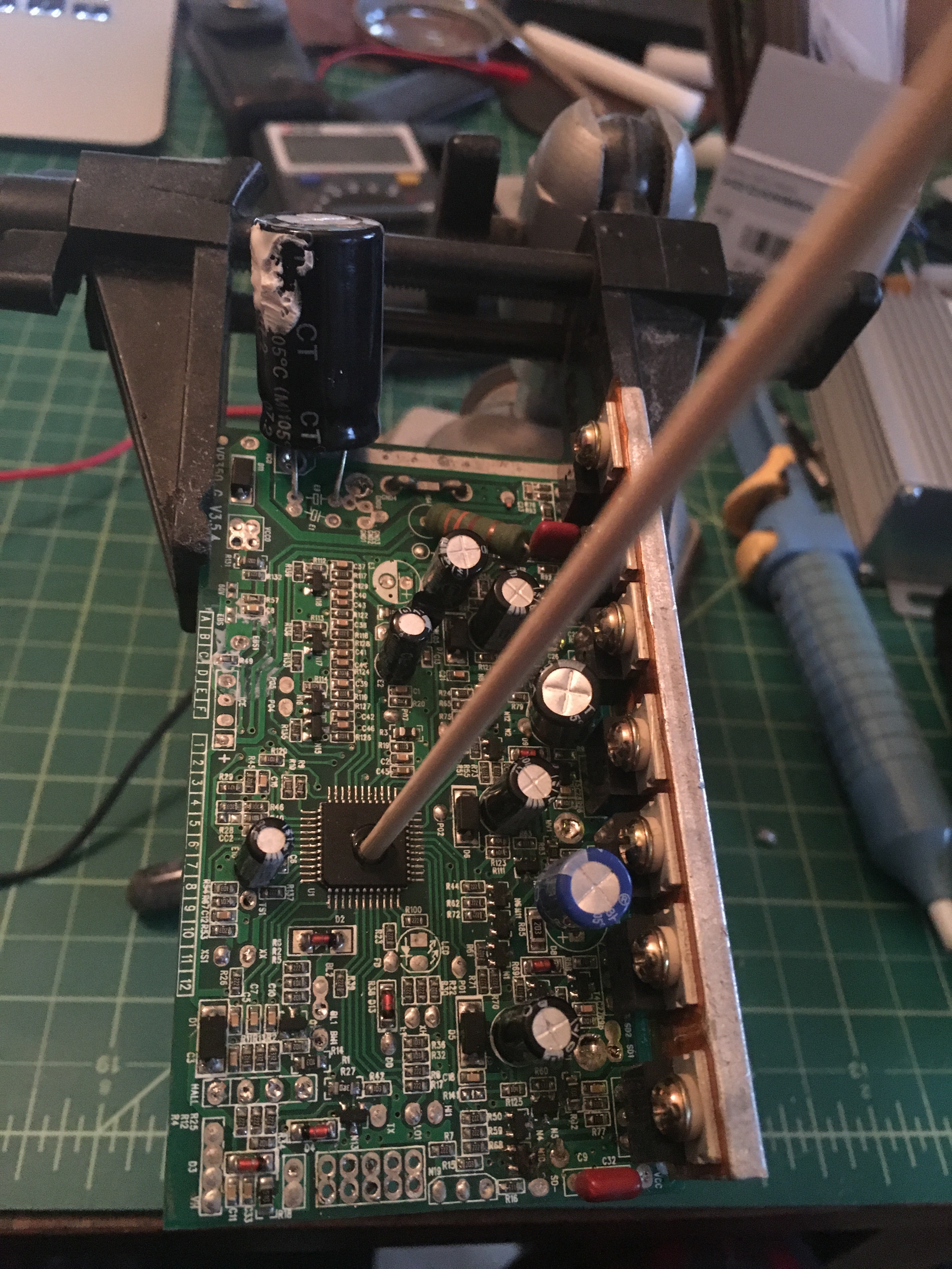
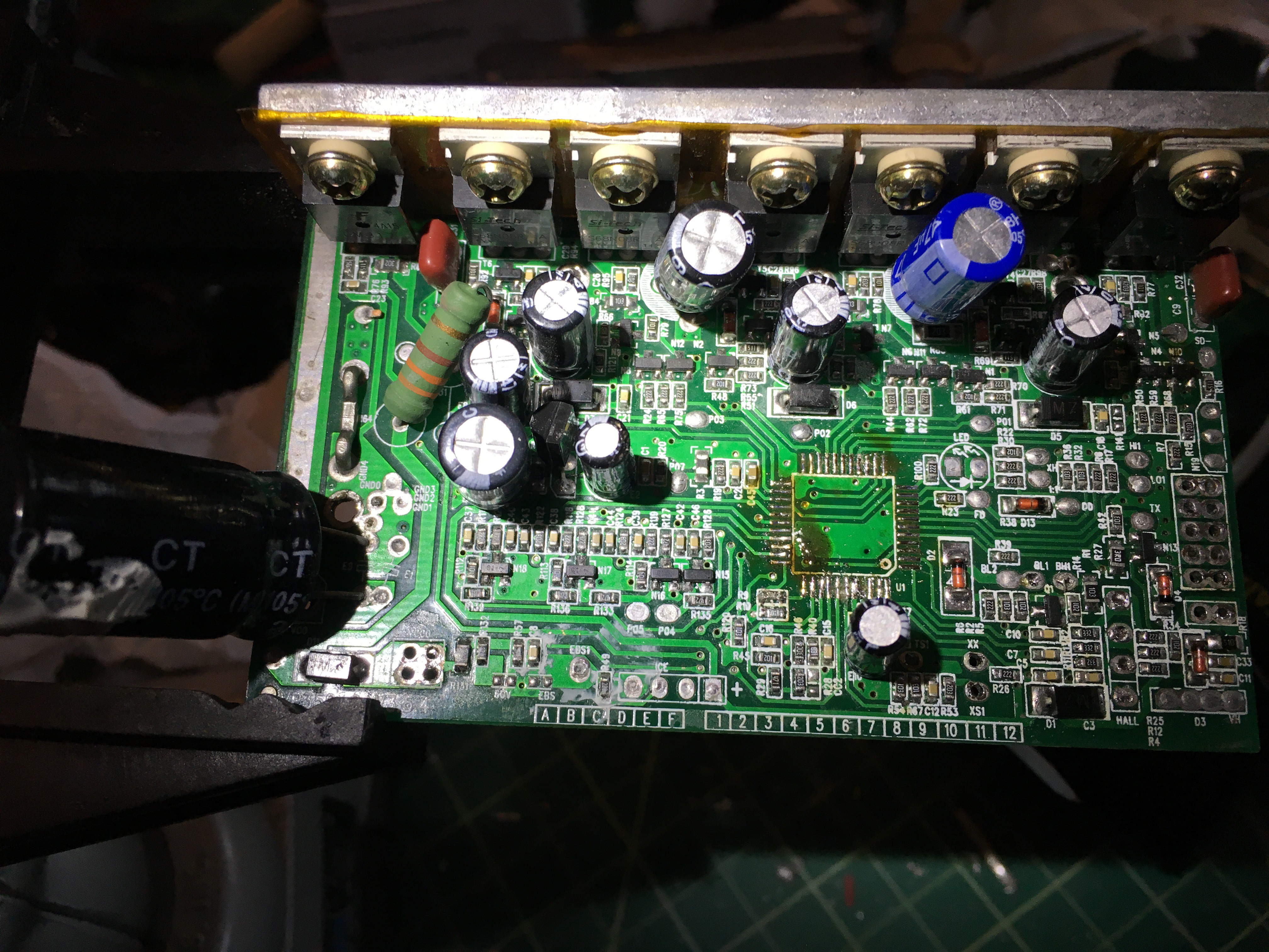
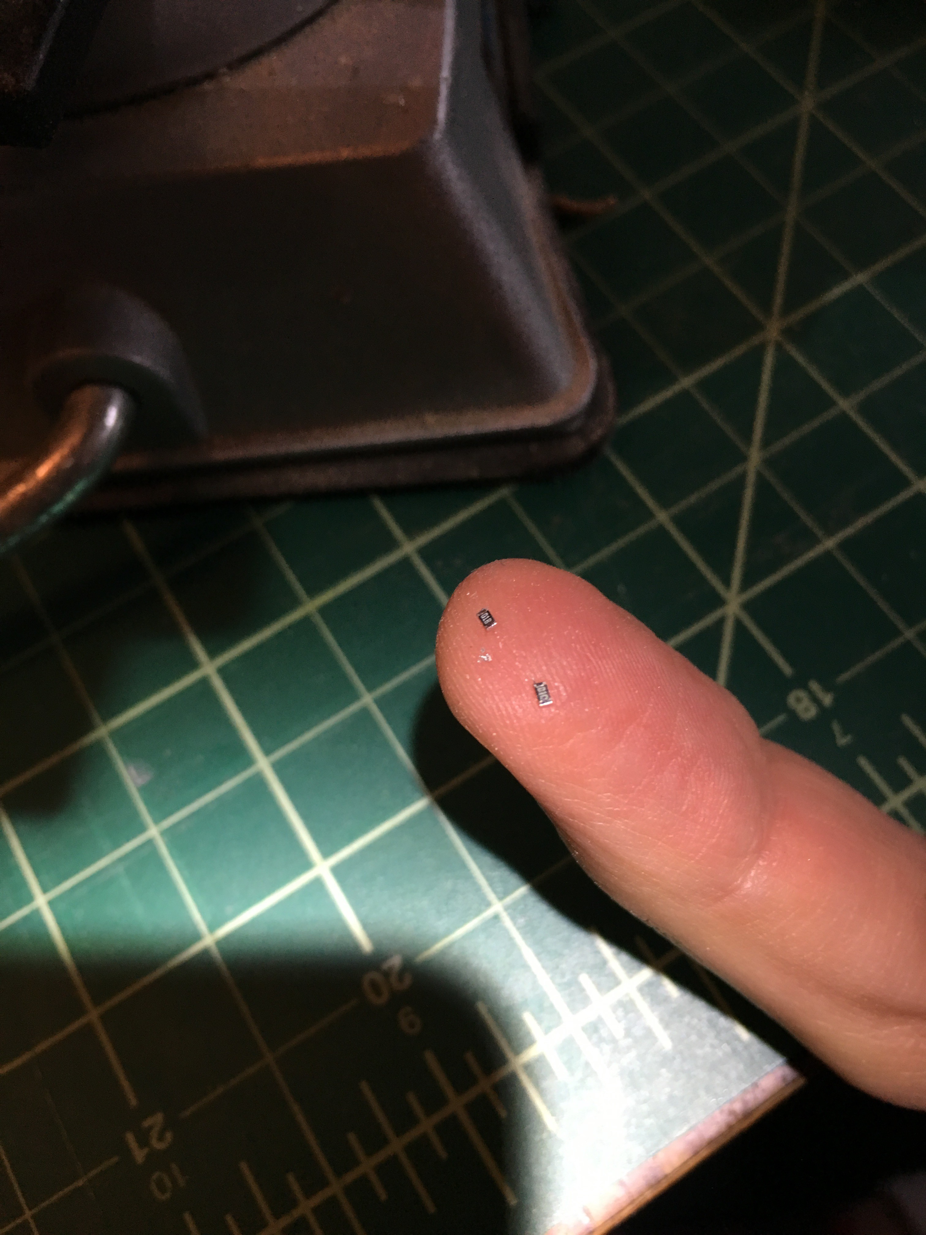
... not too bad. Two resistors came up with the desoldering, but (a) they're part of the mystery circuitry and (b) I fished them out of the desolderer and put them back in place anyway.
So I clearly don't want to jam current down the motor until I know what I'm doing. So let's start with the hall sensors, shall we? I have 5 pins related to said, and I've got a Teensy 3.1 lying around that I want to use to control two controllers simultaneously (keeping them in sync). Looking at the schematic for this piece of the circuit, I think it should work with a +3.3v drive instead of a +5v drive, and the Teensy is 5v tolerant of the return. So the controller is wired back up to a motor; some enameled wire comes out and is soldered to the right pads for the CPU, then soldered to the teensy; and a quick program is whipped up to just read the sensors and report when the one on pin1, pin44, and pin43 changes state.
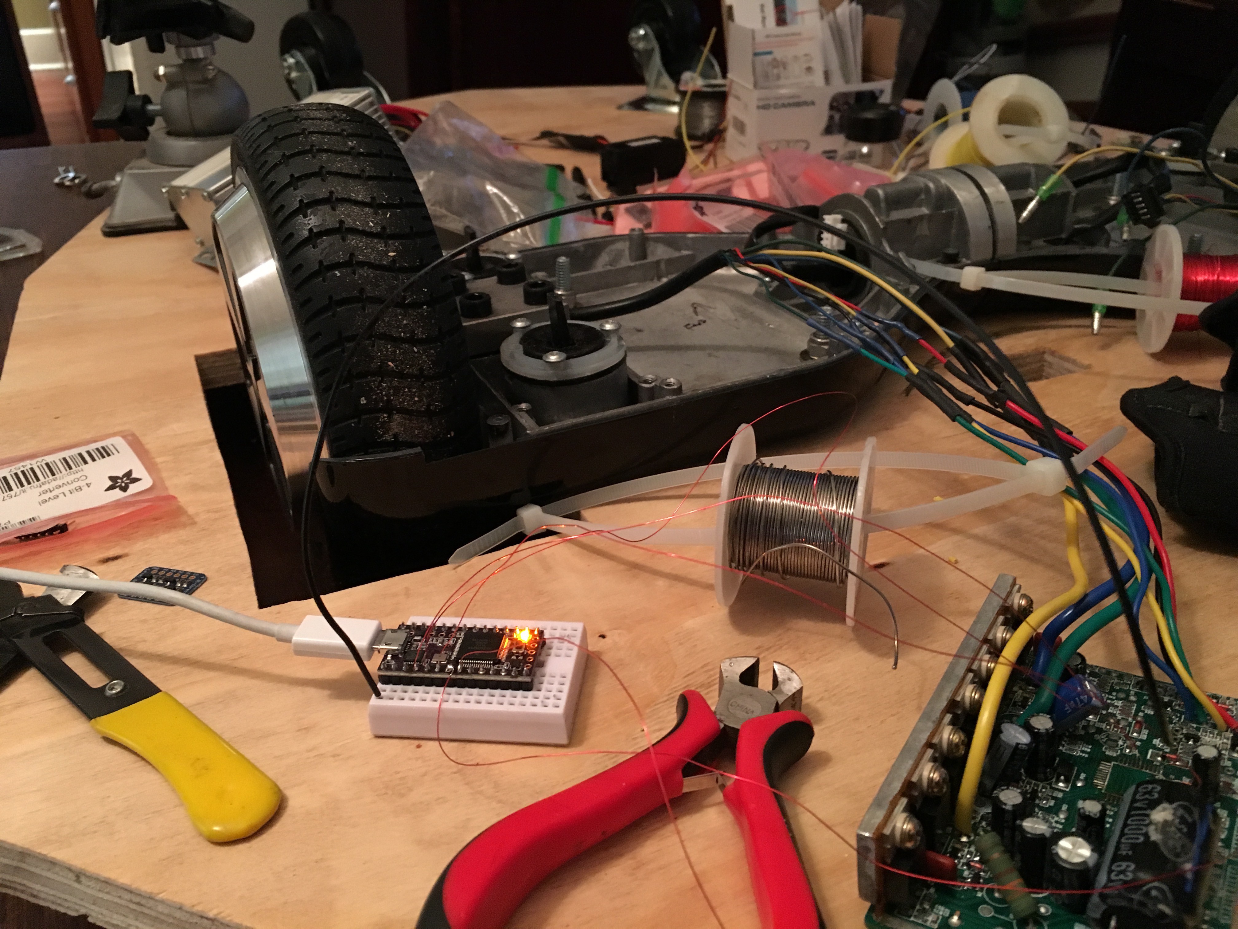
Apply +36v to the nameless controller - no smoke, that's a good sign - and watch the terminal output while spinning the wheel. First in one direction:
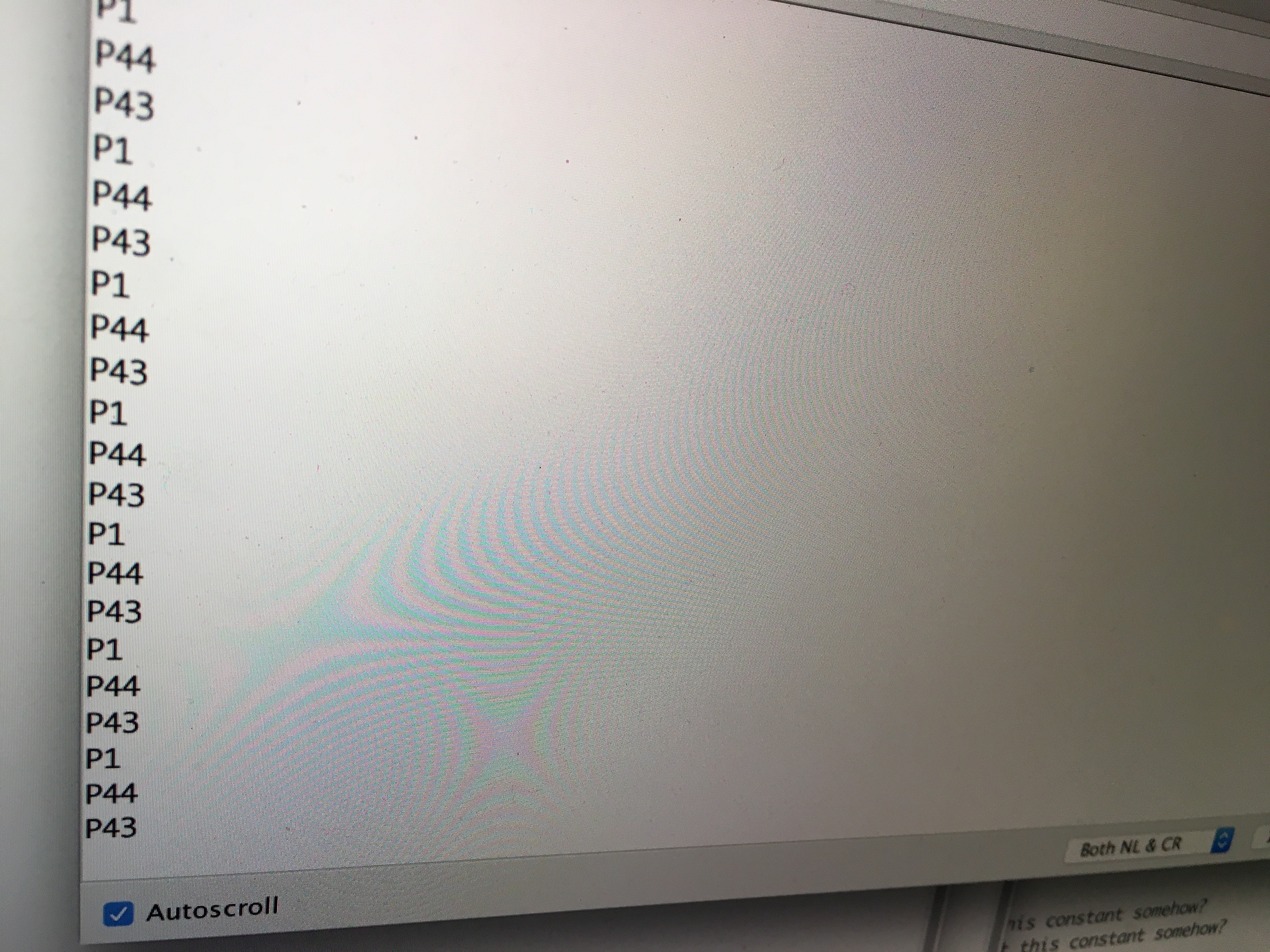
... damn, that's satisfying. 1 -> 44 -> 43, very reliably; and it's really easy to feel when the motor is changing phases, so it's no problem to cross-check that it's doing the right thing. Feel the bump in the motor, see the output in the terminal. And does it work backwards?
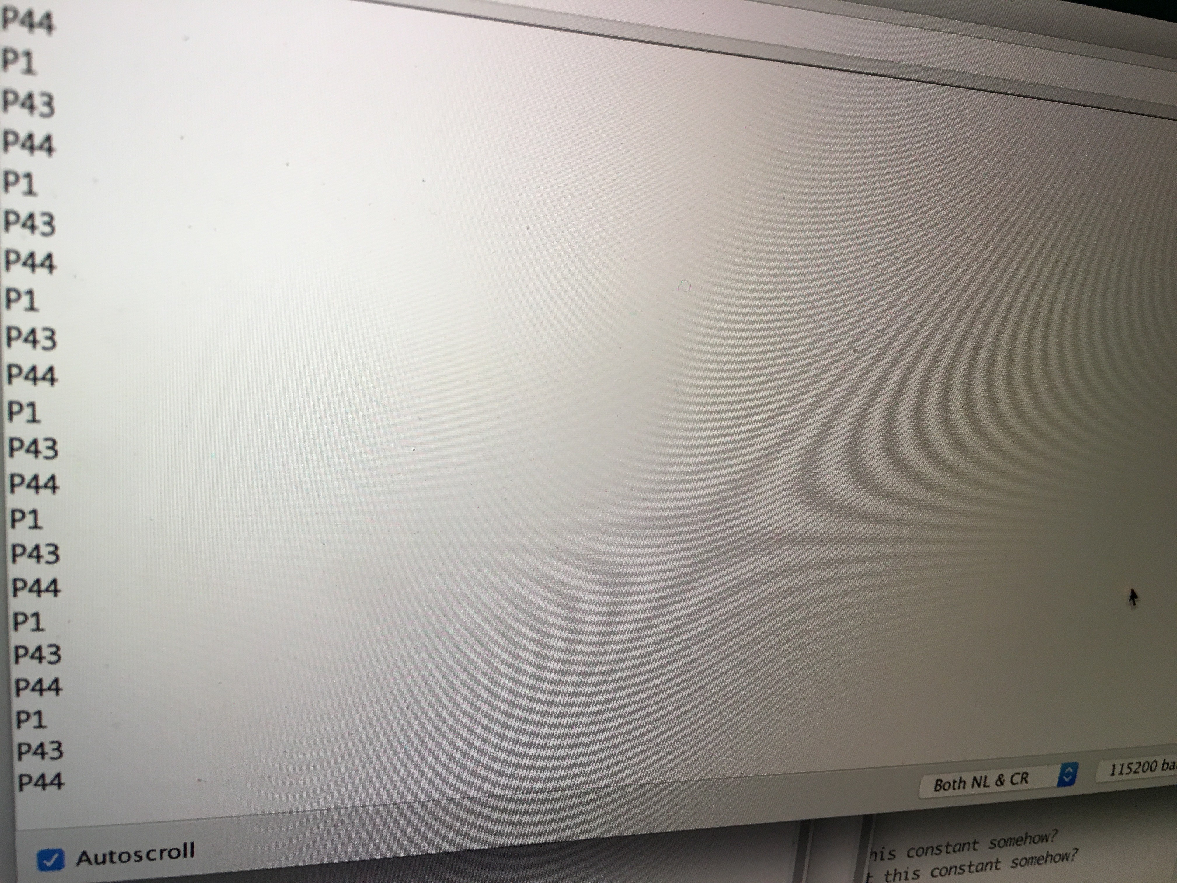
Sweet! 43 -> 44 -> 1, exactly as I'd expect.
The other two pins look like they're some control circuitry for how and when we feed power to the hall sensors. For the moment I'm not doing anything fancy with them (pins 5 and 6, if you really care) but I've got them wired up just in case.
This is starting to look like it's got a chance of succeeding. Next up, I guess I start trying to make it turn!
 Jorj Bauer
Discussions
Become a Hackaday.io Member
Create an account to leave a comment. Already have an account? Log In.