I had a Kemitron OP-3 card in my collection, which appeared to be a relay isolated output port. I believe these cards were used in Kemitron computers to control laboratory equipment, i.e. to turn apparatus on and off at predetermined intervals. As the Kemitron bus is so similar to the Interak bus, could I get it working in my Interak system?
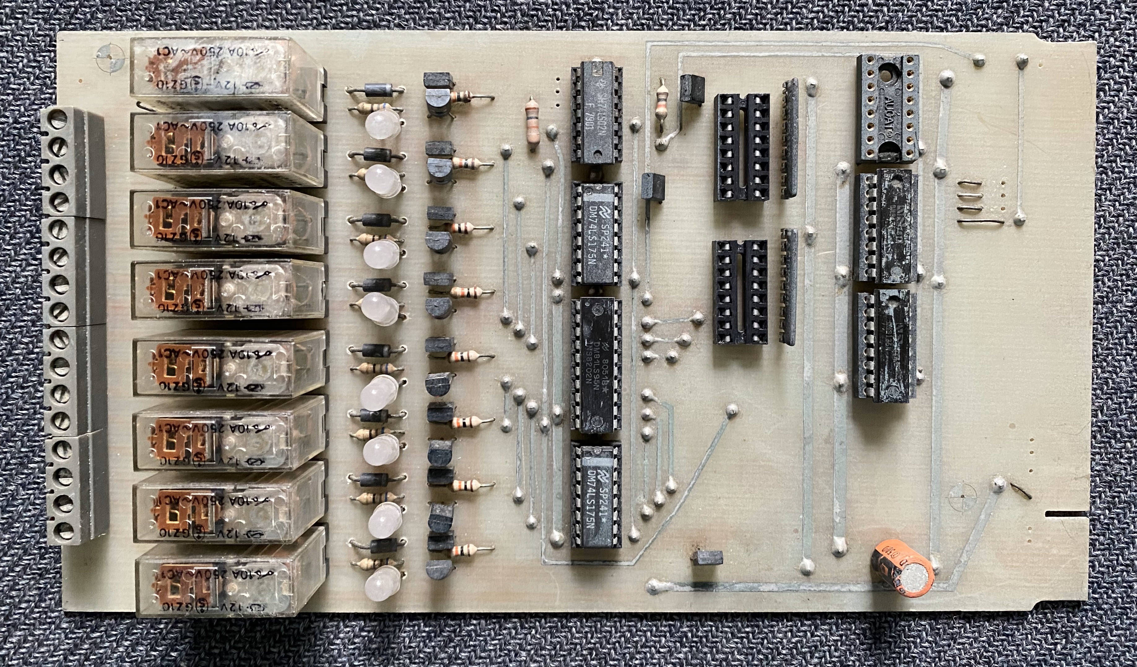
The board appeared to have three ICs missing, so the first task was to reverse engineer the circuit. I quickly realised two of the missing ICs were in fact not ICs, but 8-way DIL switches, used to set the address of the card. Tracing the wiring from the DIL switches revealed the three ICs alongside the edge connector all appeared to be the same, and as two were DM8136N “6-bit Identity Comparators”, it seemed logical the third was too. These comparators are relatively rare nowadays, and command quite high prices, but to complete my card I went ahead and placed an order for a replacement.
The replacement IC finally arrived, and when installed together with two new DIL switches, my OP-3 card was once again complete. I set the card address to 0010h, slid it into my Interak cardframe, and powered-on. There was no smoke, which is always a good sign, and my Interak was still working!
I wrote a short piece of 8080 ASM code to output “3” to port 0010h and ran it. “Clunk”. The lower two relays operated and their associated LEDs illuminated. Things were looking good. I then wrote a slightly longer piece of code to read a digit from the keyboard and write it to port 0010h. Success! Though the largest number I could enter as a single digit was 9. A further code modification and I could read two digits, multiply the first by ten, add it to the second, and write the result to port 0010h. That didn’t work!
Entering 0 to 9 worked as before, but 10 appeared as 0, 11 as 1, 12 as 2, and so on. Was my code at fault? I couldn’t see anything wrong.
Fast-forward a couple of days, and I stumbled across a not overly well documented issue with how the Z80 writes to hardware ports. If you use the 8080 OUT instruction (which I was) then the Z80 puts the port address on the lower 8 bits of the address bus (to address the port) and puts the contents of the accumulator on the upper 8 bits. Who knows why that was considered a good idea! Once I discovered that, I realised the upper address bits were changing the port address, as my OP-3 board was decoding all 16 address lines. Sometimes I wasn't writing to the port at all! (It’s actually slightly more complicated than that, because not all of the address lines are connected by default, but we’ll come back to that).
Realising the issue, I pulled the top address decoder chip (the one that was missing originally) which stops the upper 5 address lines being compared. The three lines below that are actually un-jumpered on the PCB, so the upper 8 address lines are now ignored. And that's it fixed. It no longer matters what weirdness the Z80 does on the upper half of the address bus, as it's not checked. My card was now fully working.
It seems that the OP-3 card was flexibly designed to work with a number of different processors. In a Z80 system, an IC needs to be omitted and 3 address lines left un-jumpered, but it could also use all 16 address lines with the IC and jumpers fitted, should that configuration be usable by a different processor.
A bit late in the day, I decided to draw-out the complete reverse-engineered schematic. Had I done it sooner, I’m sure it would have made the problem a lot more obvious! The schematic is provided below, and I believe it to be correct, but please remember it is reverse engineered and not from any official source.
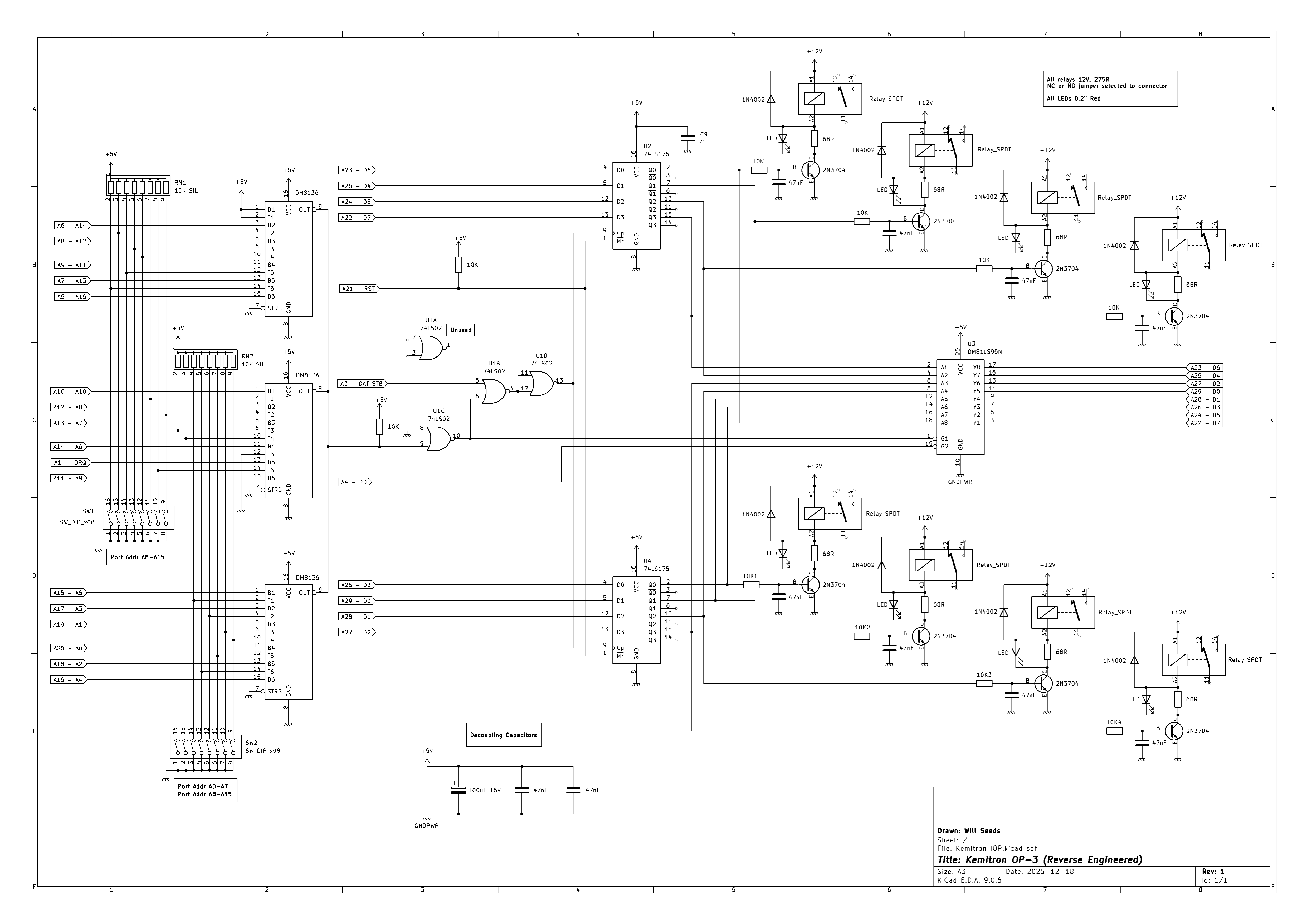
From the schematic, a couple of interesting features are noticeable. Firstly, the LED connections. Rather than using a standard series current-limiting resistor, the LEDs are connected in parallel with low-value resistors. The resistor values have been carefully selected, to provide sufficient voltage drop across the resistor to forward bias its associated LED, illuminating it when current flows through the relay coil.
Secondly, a DM81LS95N Tristate Octal Buffer allows the OP-3 port to be read, to determine its status. I initially thought the OP-3 might be a bidirectional port, before realising the buffer simply allowed the ports latched configuration to be read.
Overall, the OP-3 is a simple but interesting card, with a number of novel features. Perhaps one day, I'll be able to use it in a Kemitron!
Discussions
Become a Hackaday.io Member
Create an account to leave a comment. Already have an account? Log In.