 Smeef
SmeefMy Thingiverse page for this project: https://www.thingiverse.com/thing:5155241
0%
0%
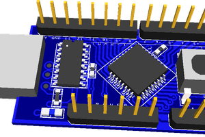
Arduino Joystick Mouse
A tiny Arduino-powered USB joystick mouse with 3D printed enclosure and right and left click functionality
Become a Hackaday.io member
Already have an account? Log in.
Just one more thing
To make the experience fit your profile, pick a username and tell us what interests you.
Pick an awesome username
hackaday.io/
Your profile's URL: hackaday.io/username. Max 25 alphanumeric characters.
Pick a few interests
Projects that share your interests
People that share your interests
 Lexcis
 Mo Badr
 Amirreza Nasiri
 Jean Noel